a14g-final-submission-t23-mcu-wanda-lock

a14g-final-submission
* Team Number: 23
* Team Name: MCU - Wanda Lock
* Team Members: Tao Liu & Chihan Zheng
* Github Repository URL: https://github.com/ese5160/a14g-final-submission-t23-mcu-wanda-lock.git
* Description of test hardware: embedded hardware, Windows laptop, IR sensor, QR code reader, LCD screen, servo, battery, etc
1. Video Presentation

2. Project Summary
Device Description
Wanda Lock is an intelligent door lock which is easy-to-use, cheap but still maintains security.
Wanda Lock is focusing on realizing common functions of door locks, but ensuring a lower price and is still capable of avoiding security issues.
Wanda Lock requires user to provide email to receive a key of QR code. This helps to avoid the situation where people steal the name and password and can also open the lock. Using personal email for identification and security is a common strategy on the market, so using this instead of camera is an effective and much cheaper way to ensure both functionality and secuirty.
Internet Usage Wanda Lock has 3 different interfaces for 3 kinds of users: Guests, Owner, Administrators
a. Guests Guests can send personal information to owner’s interface such as name, password and email.
b. Owner Owner can see guests information, then can decide whether to open the lock and whether to store guests information into local database. Owner can be notified by sound when guests are coming and the lock is open/closed. The lock status is also indicated by a LED on the interface in case owner is not capable getting access to the sound notification.
c. Administrators Administrators can use their interface to realize On-The-Air-Firmware-Update by simply pressing a button on the website. The update progress is shown on real time.
Inspiration
There are so many smart lock on the markets, why do we want to design another one?
Price and Potential Customers Are What We Focus on
Firstly, many smart locks on the market are over $200 just because they use cameras. Then, why not use email and QR code reader to create a cheap and secure lock?
Secondly, do many people really need our lock? Absolutely! Nowadays, people especially businessmen spend much time working outside. They need a way to monitor their door on real time and let their guests to come in when they are not at home.
Besides, in a modern world, everything is driven to be controlled remotely and everybody will use smart devices. Thus, since people need it, we build it.
Device Functionality
Our project is a simple smart door lock system that makes access easy for both guests and owners:
Guest Access Request: When a guest arrives for the first time, they scan a QR code and fill in their information. This sends a request to the owner. Owner Approval: The owner receives the request and decides whether to grant access. Also owner can store the guest’s info for future visits. Access Granted: Upon approval, the guest receives an email with an access QR code. They can just show it to the door’s QR code reader to unlock it.
With this system, guests can easily request access, owners can manage approvals, and access is granted seamlessly via QR codes.
Our project comprises five main components:
3 sensors (IR sensor, QR code reader, and buttons) and 2 actuators (LCD screen and servo motor).
IR Sensor: Detects if a guest approaches the door. When triggered, it activates the LCD screen to display information.
QR Code Reader: Recognizes QR codes from guests. If the QR code matches stored information in the microcontroller, it signals the servo motor to unlock the door.
Buttons: Guests use buttons to request access. Pressing the button triggers the LCD screen to display a QR code for scanning.
LCD Screen: Displays prompts and QR codes for guests to make access requests to the owner.
Servo Motor: Simulates the lock status. When activated, it indicates the door opens.
Challenges
Firmware
When we tested the QR code reader, the reader always returned 0s to MCU even if the I2C communication is normal. Later, we found although manufacturer says a register can be written to control the LED, the read-back data will be all 0 if we write to the register before we read from the reader. Besides, the interval that the reader reads QR code also matters. If we uses 400ms instead of 200ms, the read-back data is also 0.
We store a large QR code into a 2D array. However, If we define the array as a global variable, the memory is not enough. Thus, we moved it into a function so that it can be in the stack, then the stack has enough space to store the array.
When integrating all peripheral drivers together, the FreeRTOS stack always overflows. Thus, we had to adjusted the task size for each task. We should’ve used High WaterMark function to estimate the size of each task instead of just trying random task sizes.
Hardware
We didn’t assign the SPI LCD screen pins to the Sercom specifically, so later our LCD cannot have normal communication between MCU. Thus, we rearranged the pin assignment for LCD and did rewiring work using test points for unused MCU pins.
We planned to use PA21 to generate PWM through TCC0, but it didn’t give any output. Thus, we had to changed PA21 to PA10 which generated correct PWM pulse using TCC0.
Prototype Learnings
We did many rework and rewiring. It resulted from many reasons. The first reason is that we didn’t consider much about the functions of each pin when we did pin assignment. If we want to use I2C peripherals, we need to find Sercom pins instead of other random pins. Some pins have specific functionality so we need to do careful pin assignment for every single pin according to what we want the pin to do.
Even if we assigned correct pins, sometimes they don’t work correctly either. Thus, route every unused pins to testpoints! You don’t want to stare at the MCU when you want to rewire but there is no testpoints on the board. Even if you already have jumpers for the power circuits, add test points as well! If the jumper pads are ruined, you still have testpoints! Adding testpoints not only helps test signals, but also help you out when you want to do rewiring work.
Please use tapes to fix the test wires onto the board, or you will 100% pull the pads off your board. Sometimes, you don’t even know when the pads disappear. Therefore, use insulated tape to fix test wires onto the board in case the wires are pulled up with pads accidentally! After you don’t need the test wires, just desolder them off the board.
Arrange the locations of connectors on your PCB with deep consideration. You don’t want the situation where you connect the peripheral into the connector and can never pull it out because another connector block the way that there is not space for your little fingers. Take us as an example, our QR code reader sometimes goes wrong, so we have to replug it into the connector. However, there is another LCD connector right next to it blocking our way, so we can hardly pull the QR code reader connector out after we plug it into the connector designed for it on the board. This time we are lucky, because we can replug the connector on the QR code reader itself instead of the one on the board, but what if the connector on the QR code is soldered so that we can only replug the connector to the board?
Download the documentations you need from Microchip in case the website crashes for weeks!
Next Steps
Although using QR code as ID verification is a unique section of our design, the QR code door key is static, which means it’s still not really secure. Thus, we should use different QR code as the door key so that one QR code can only be used once.
We also used an QR code as a link to our Node-Red. However, this QR code drawed on the LCD screen pixel by pixel which means it wastes much space in memory to store the pixels of QR code. A better way is to store the QR code in the SD card of LCD and transfer the QR code directly to LCD screen.
The refresh rate of our LCD screen is slow now. We should come up a better communication between MCU and LCD to realize a faster LCD display.
Although the IR sensor is highly sensitive and accurate, it’s better to have options of different detected distances, such as 10cm, 20cm, etc. For now, our detected distance is fixed.
For now, our servo motor acting as a door lock is closed after a fixed time interval when we open the lock. We can improve it by closing the lock only when the door is closed instead of being closed based on certain time interval.
We used FreeRTOS vDelayTasks function to have a certain delay. It worked well until we integrated all peripherals together. The delay became inaccurate, thus we should come up with a better way to generate accurate time delay.
Takeaways from ESE5160
ESE5160 goes through the main parts of embedded system design flow, starting from coming up with new idea, to make the idea come to life. We need to decide what components can help realize our idea, which power regulators we need to use, what pins they will occupy.
Then, we need to draw schematic to connect everything together, after which we design PCB where we need to work as a good “City Planner”. We have to pay attention to high speed signal routing, power routing and components placement, etc. During the PCB manufacture, we write drivers for each peripherals in advance and use our dev board to test their functionality. This is where we learn how FreeRTOS and different communication protocols work.
After the PCB comes back, we test powers, do load tests and check thermal images one by one and test functionality of button, LED, MCU, WiFi, etc. This is where we learn how to de-solder and solder components, using solder wick, flux, fly wires, … Then, we integrate all peripherals to our customized PCB and we use Node-Red to realize remote control and monitoring through MQTT.
Beyond these, we also learned how to implement basic bootloader and firmware update, especially OTAFU through HTTP and we can initiate OTAFU through Node-Red remotely based on MQTT.
Stepping out the electrical engineering world, we also worked as mechanical engineers. We 3D printed our customized PCB so that we could have a better understanding of how the PCB looks like and prepare a better and suitable casework. In the end, we designed and 3D printed a wonderful casework composing of three parts which acts as a door with all of our components (and even our names :)) on it. We also learnt how to choose different material and hardness for 3D printing.
Reaching here, we have designed a portable IOT prototype which has desired function features including basic functions, WiFi, OTAFU as well as a desired mechanical structure.
Project Links
3. Hardware & Software Requirements
HRS
HRS01 - The foundation of this project shall rely on the SAMW25 microcontroller.
Achieved. Whole project is designed and implemented based on SAMW25. We use the Dev-board SAMD21 (embedded with SAMW25 chip) for testing and debugging in the beginning of project.
HRS02 - The IR Sensor TSOP38238 shall detect the proximity of a person to the door. The system will register anyone who remains close to the door for a duration of 3 seconds. The Sensor shall communicate with the microcontroller via GPIO bus.
Partially Achieved. We changed IR Sensor with the MH Infrared Obstacle Sensor Module instead of TSOP38238 which is actually an IR receiver instead of IR detector. Anyone that is close to the door will trigger the Infrared Module instantly. It indeed communicates with MCU via GPIO bus.
HRS03 - A QR code Reader shall be employed to extract information from the code presented by the visitor. The Reader shall communicate with the microcontroller via GPIO bus.
Partially Achieved. We do implemented extracting information from the code using Tiny Code Reader Module, but this module communicates with MCU via I2C bus.
HRS04 - The Servo-motor SG92R will act as a simulated lock. The motor shall be activated when a visitor successfully presents the correct QR code to the QR code Reader.
Achieved. After visitor present the QR-code to the Tiny Code Reader, the servo-motor will trigger instantly to indicting the lock is open. After few seconds the servo-motor will return to the original state indicting the lock is closed.
HRS05 - A 1.8” diagonal LCD shall be used for the user interface. The display shall communicate with the microcontroller via I2C bus.
Partially achieved. We use LCD screen to show welcome messages in every cases and also the 25x25 QR-code. However, it communicates with MCU via SPI bus since we changed for another SPI LCD screen instead of the previous I2C LCD screen.
SRS
SRS 01 - The microcontroller should check the response of the infrared distance meter every 5 seconds and use 1bit to indicate whether there is a visitor coming.
Partially Achieved. The vTaskDelay function is not accurate in our project. Ideally we wanted to delay 5 seconds, but vTaskDelay(5000) cannot make stable 5 seconds delay. So we changed to vTaskDelay(999999) for a relative long delay which in practice presents around 1-2 mins actual delay.
SRS 02 - If the microcontroller recognizes a visitor, it shall fetch a 80*80 URL QR code from the SD card (NVM with 256KB via SPI) and send it to the LCD screen.
Partially Achieved. We display the LCD screen with only 25*25 size QR code because of limited pixels on LCD. Also we didn’t implement fetching the QR code from SD card. We just simply plotted the code pixel by pixel in the “for” loop. That’s why displaying the code takes quite long time.
SRS 03 - Visitors should provide their name, password and email (< 150Bytes) in the user interface. If visitors click the “Request” button in the interface and the interface shall prompt a response to the microcontroller.
Achieved. When visitor type in their name, password, email, and then click “Send Info to Owner” button, these information will show on the Owner interface. Also a prompt window shows indicating a guest is coming!
SRS 04 - When the visitor makes response in the interface, the microcontroller shall receive the response and extract name, password and email from the response (into 3 char arrays).
Achieved. We used char arrays to store these 3 information.
SRS 05 - The microcontroller shall verify visitors’ info with existed users’ Info database and send control signal to the motor for the lock if verification passes. It shall be also capable of storing the info into memory that is an internal RAM with 32KB.
Achieved. If visitors’ info matched to the existed user’s info in database, visitor would not get access from the owner by QR code. They can just unlock by typing his/her name & password.
SRS 06 - If verification of info fails, microcontroller shall send the info and URL of owner interface to owner via email. Owner should make decision in the interface and microcontroller shall receive the response and send a QR code to visitors via email or via displaying on visitors website interface.
NOT Achieved. If verification of info fails, only the prompt message will show on the LCD screen and owner can just see the lock status remain off on his/her interface. If the visitor still want to get access to the lock, he/she should wait for the permission from owner.
SRS 07 - After visitors display the QR code to the QR code reader, the microcontroller shall receive the request and make decision to control the motor and the LCD screen shall display some prompted messages.
Achieved. If the information in QR code displayed by visitor has the same information as in MCU, it means this visitor use the right access QR-code so that MCU can control the motor on, display welcome message on LCD screen indicating the lock is open.
If someone uses a random QR code, the info in this code is not corresponded to the info stored in MCU, the motor will not be triggered and message on LCD will show “Incorrect QR code!”.
SRS 08 - The microcontroller shall track the status of the power of the board, Wi-Fi module and the lock by controlling three LED lights.
Partially chieved. Only the power LED indicates correctly. We did not program the other two LEDs.
SRS 09 - The microcontroller shall be capable of making LCD screen to present both QR code and messages.
Achieved. We use LCD screen to present both QR code and some other welcome/prompt messages.
SRS 10 - The lock should have two modes to adapt either case of whether owner is at home or not.
NOT Achieved. Our lock is just either on or off using servo-motor and it’s controlled by MCU or owner instead of being mannually opened.
4. Project Photos & Screenshots
Wanda Lock
 </img>
  </img>
  </img>
  </img>
PCBA
 </img>
  </img>
 </img>
  </img> </img>
 </img>
Node-RED
 </img>
  </img>
  </img>
  </img>
  </img>
  </img>
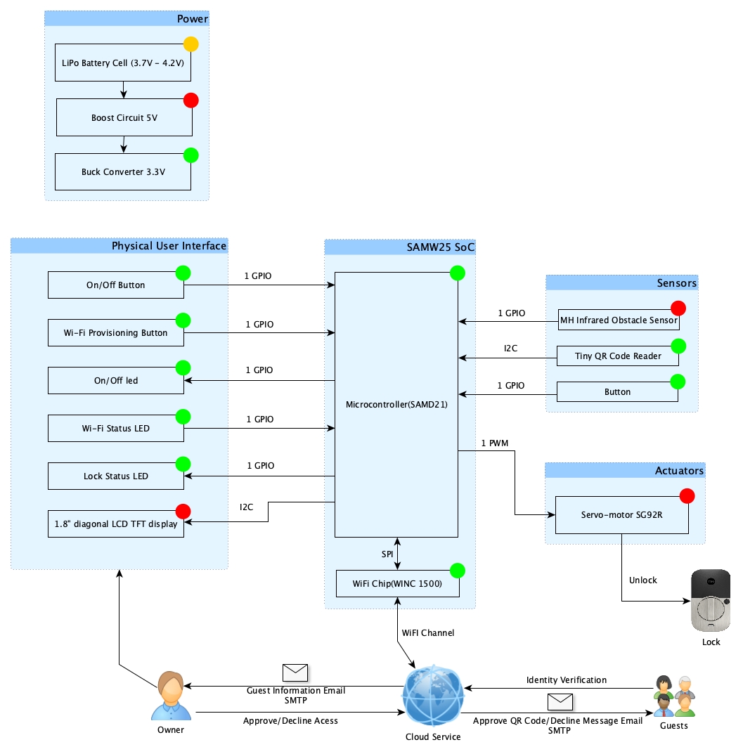
System Block Diagram