a14g-final-submission-t20-gold-rush

a14g-final-submission
* Team Number: 20
* Team Name: Gold Rush
* Team Members: Shijia Jiang and Chenyu Ye
* Github Repository URL: https://github.com/ese5160/a14g-final-submission-t20-gold-rush.git
* Description of test hardware: PCB, Ultrasonic sensors, I2C Driver, LCD Screen, Dell G3, Lenovo Y9000P
GitHub Pages Link: https://ese5160.github.io/a14g-final-submission-t20-gold-rush/
1. Video Presentation
https://github.com/ese5160/a14g-final-submission-t20-gold-rush/blob/4e08b700898a72a7467feca97722ca8dd32b9808/Team20_Final%20Video.mp4
2. Project Summary
Our group is going to make an ultrasonic radar controlled by Node-RED dashboard detect objects 180 degree ahead. The equipment set up a 2-Dimension diagram to show the positions by circle and ranges of height by different color of surrounding objects on LCD, the data of distance, angle and height is shown on computer terminal via UART. The key technical problem is how to detect the edge of projects. To achieve that, we assume that when the distance sensor detects a mutation more than 10cm, then considered it as an edge, that is, to start detecting the object. To obtain height data, we set the horizontal servo back to the center of object and then enable the vertical servo to measure height by the same edge-detection method.
For the internet, we can connect to our device via a remote VM to perform an OTAU upgrade of the device. At the same time, we can use the Node-RED dashboard remote control to select the motor and adjust the speed of motor rotation.
Our project is inspired by the fact that we need a radar to assist us in detecting and locating in poor field of vision conditions. Our project enhances object detection in low-visibility environments, combining radar and edge detection technologies for autonomous driving and aiding the visually impaired. This approach improves orientation, distance, and size assessments of objects, providing a practical tool for better environmental understanding.
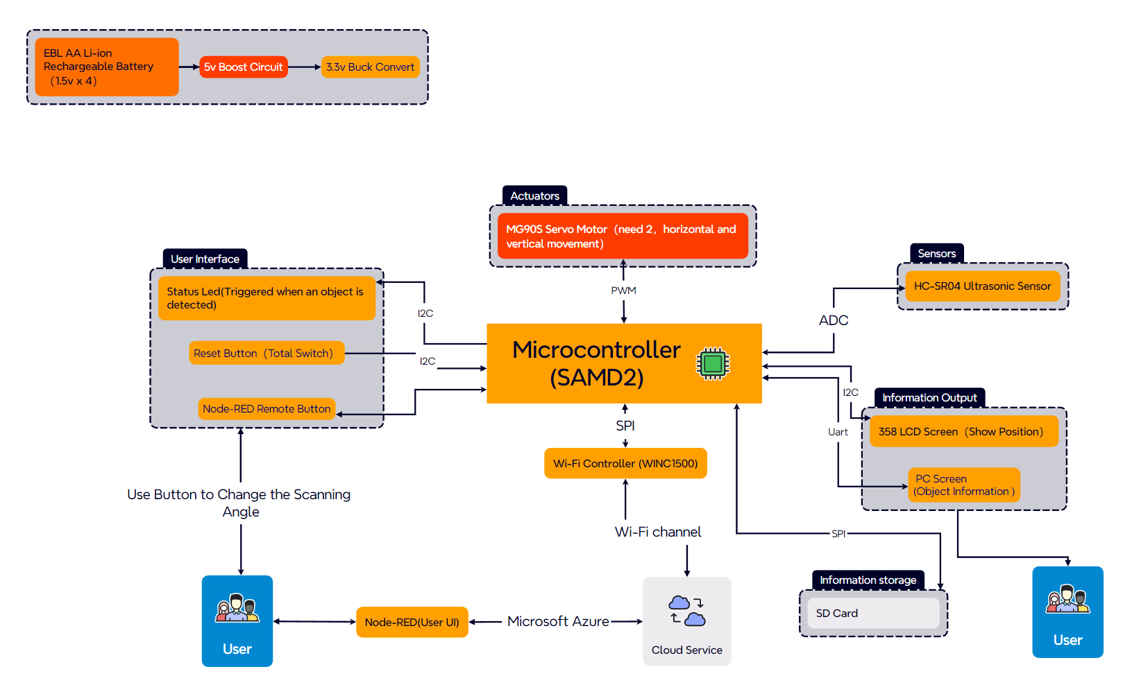
For the associated external equipment, we have four main components. First is is the ultrasonic sensor, which uses the GPIO protocol. Then, we use motor driver to drive two servo motors which connected to the PCB by I2C. And the two Servo motors carrying distance sensor for horizontal and vertical detection to obtain objects’ position and height data. Finally, LCD Screen will set up a 2-Dimension diagram showing the positions and ranges of surrounding objects by SPI.
For the difficulties, we face many problems in both software and hardware. Firstly, we found a wire for the buck circuit was not designed properly while testing the PCB. The solution was to solder a wire from the outside so that the circuit could be powered properly. At the same time, there was a problem that the I2C protocol could not be used properly on the PCB we designed. We tried many methods and finally chose to use SAMW25 to complete the control of the motor driver. In the debugging of software and hardware, we found that the computer will recognize the two motors as two drivers, and can not select the motor through the Node-RED. We were ultimately unable to solve this problem and have explained it in the video.
By building and testing this prototype, we learned to use different protocols such as SPI, I2C and Uart. We have also familiarized ourselves with the use of SolidWorks. In particular, we learned the logic of the FreeRTOS architecture. If we had to build this device again, we might choose to replace the current I2C driver due to the fact that it can’t be recognized well by our computer side and pass back data.
Our next step will be to improve the way the ultrasonic sensors work by switching to the Uart protocol for testing. At the same time, we will optimize our LCD display so that it can work and at the same time be able to perform the initially set detection tasks.
Project Links
A12G Codebase:https://github.com/ese5160/a12g-firmware-drivers-t20-gold-rush/tree/dace1975427eadbec392a1c6075341f5dd4b0297/Final_Codebase
Altium 365 Link:https://upenn-eselabs.365.altium.com/designs/CEA9C49D-7C38-4536-AB0B-07D04985FC6A#design
3. Hardware & Software Requirements
1.Hardware Requirements
Overview
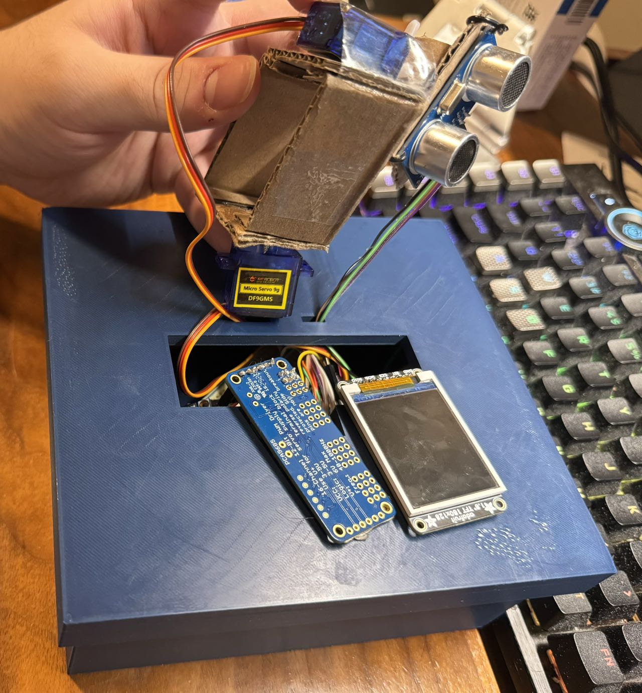
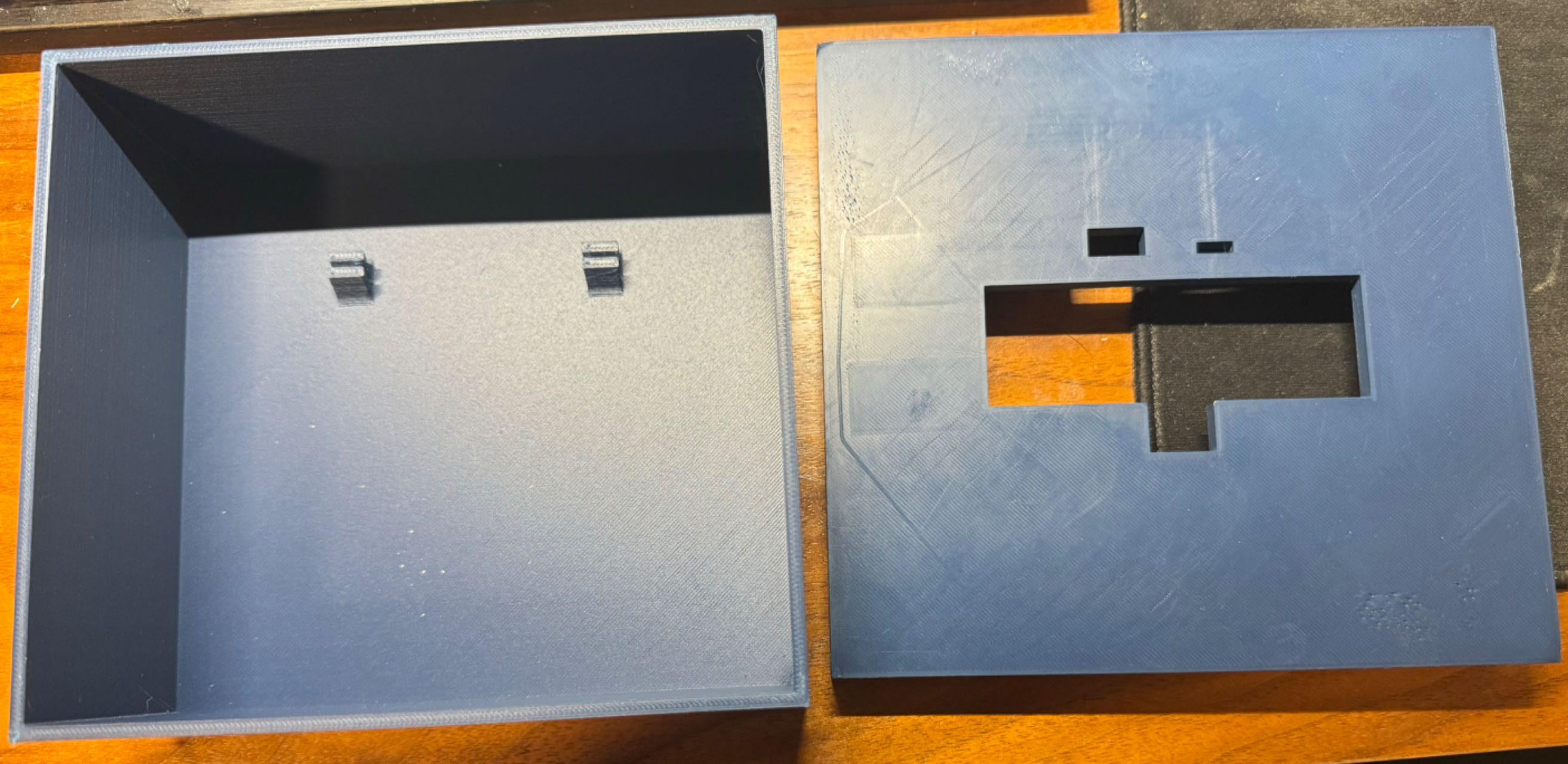
For the overall hardware situation of the project, we 3D printed the design of the enclosure, and for each sensor and driver there is a corresponding placement. For the ultrasonic sensors we realized the distance measurement and uploaded the measurement data to our cloud host. The ultrasonic sensors are driven by two motors, we realized the selection of the motors and the adjustment of the speed of rotation of the motors, which can be scanned horizontally and vertically. For the LCD screen, our microcontroller can not realize the SPI communication with him, but we put all the completed codes and tasks into the A12G, looking forward to the next upgrade. Below is the Hardware Requirements we initially developed. we will explain the problematic parts.
Details
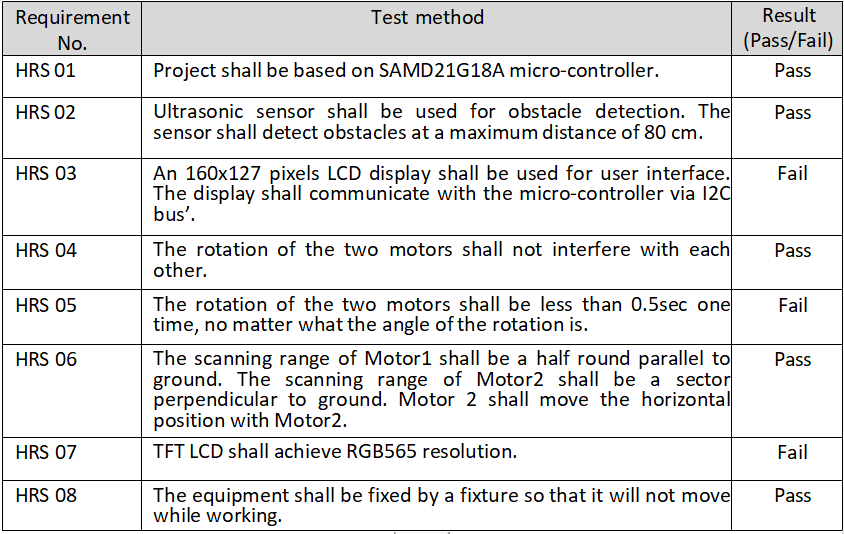 HRS 01: We have successfully implemented the power architecture for the initial design. The device operates as a standalone device using a 3.3V-4.2V Li-ion battery. A buck and a boost are responsible for converting the battery power to the required 3.3V and 6V outputs and delivering them to the other components used. Where we started with a 5V booster circuit, we ended up with an actual measured output of 6V, but still within the working range of the I2C Driver.
HRS 02:When measuring the ultrasonic sensor, our code was unable to measure the full distance information due to data overflow. We will modify the communication protocol later to use Uart.
HRS 03: Our PCB was not able to communicate SPI with the LCD, we used an analyzer to measure the signal and found that the desired signal was already displayed. Considering that the microcontroller itself is no longer able to accomplish this one task.
HRS 05: The angle of motion was not precise in our final actual measurements. After summarizing and analyzing the situation, we found that we should use an external interrupt to count the ticks accurately. At the same time, the voltage of the boost circuit is not at the initial setting of 5V, which may also be one of the reasons for the inaccurate angle.
2.Software Requirements
Overview
Our software component allows remote control of the I2C driver. At the same time, we can upload the measured data from the ultrasonic sensor to the cloud host and display it on the Node-RED user interface. At the same time, we can download the latest tasks from the cloud host to the SD card on the PCB for OTA upgrade.
Details
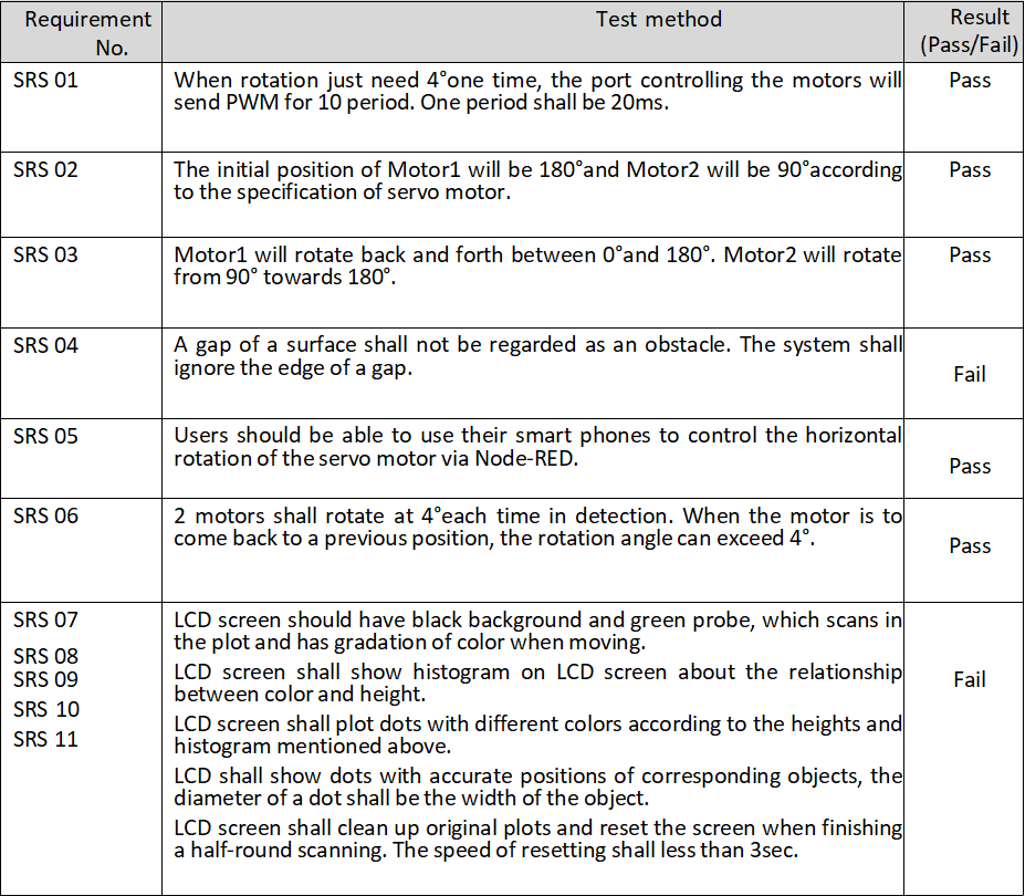
SRS 01:For our motor control, we chose to use an I2C Motor Driver for both motors. We have realized the speed selection and the interval selection for the control of their movements. However, it is not precise and will be upgraded later on for accuracy of control.
SRS 04:When we use ultrasonic sensors for measurements, there is still a problem with the triggering of external interrupts, even though we use always for timing. This resulted in many of the returned values being in an overflow state. So the gap measurement process was not accurate.
SRS 07:For the software code part of the LCD, we have placed it in the A12G. It was tested with an analyzer to the point where the required restart signal and the hexadecimal coding of the color signal were emitted. But it was not possible to finalize the complete communication with the screen.
4. Project Photos & Screenshots
Final project
 3D prints
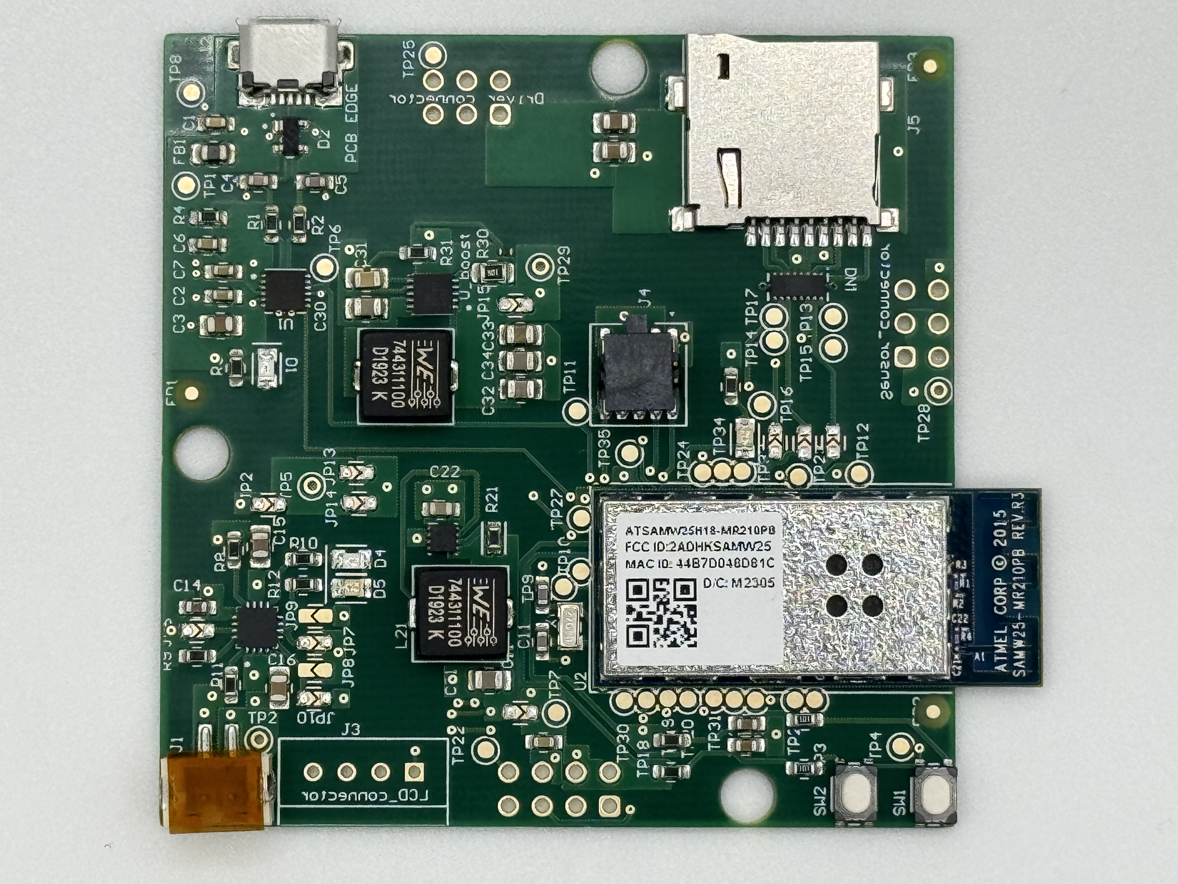
The standalone PCBA, top
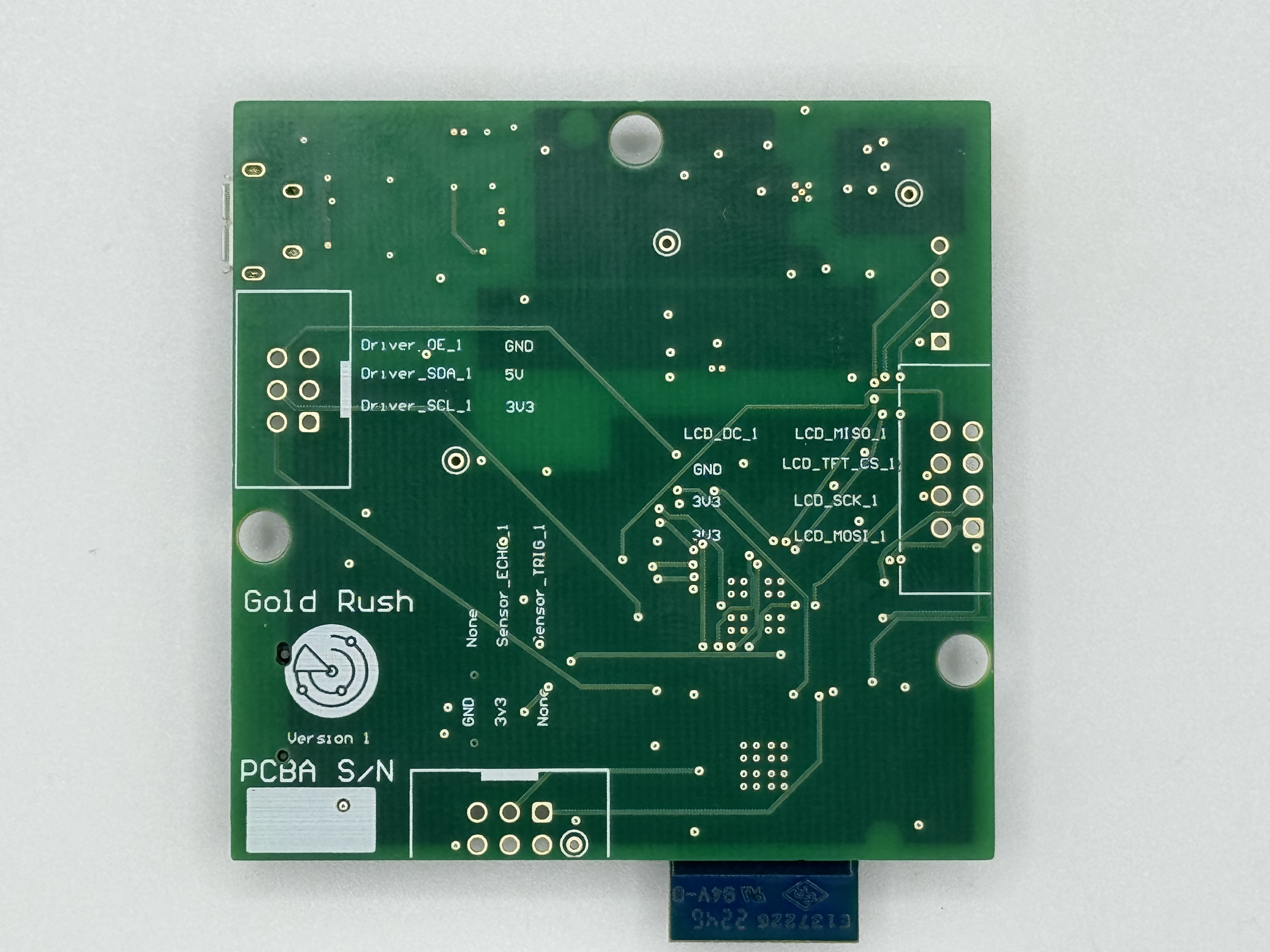
The standalone PCBA, bottom
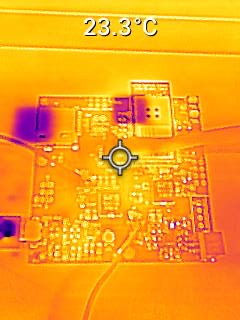
Thermal camera images while the board is running under load
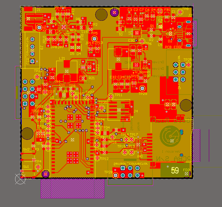
The Altium Board design in 2D view
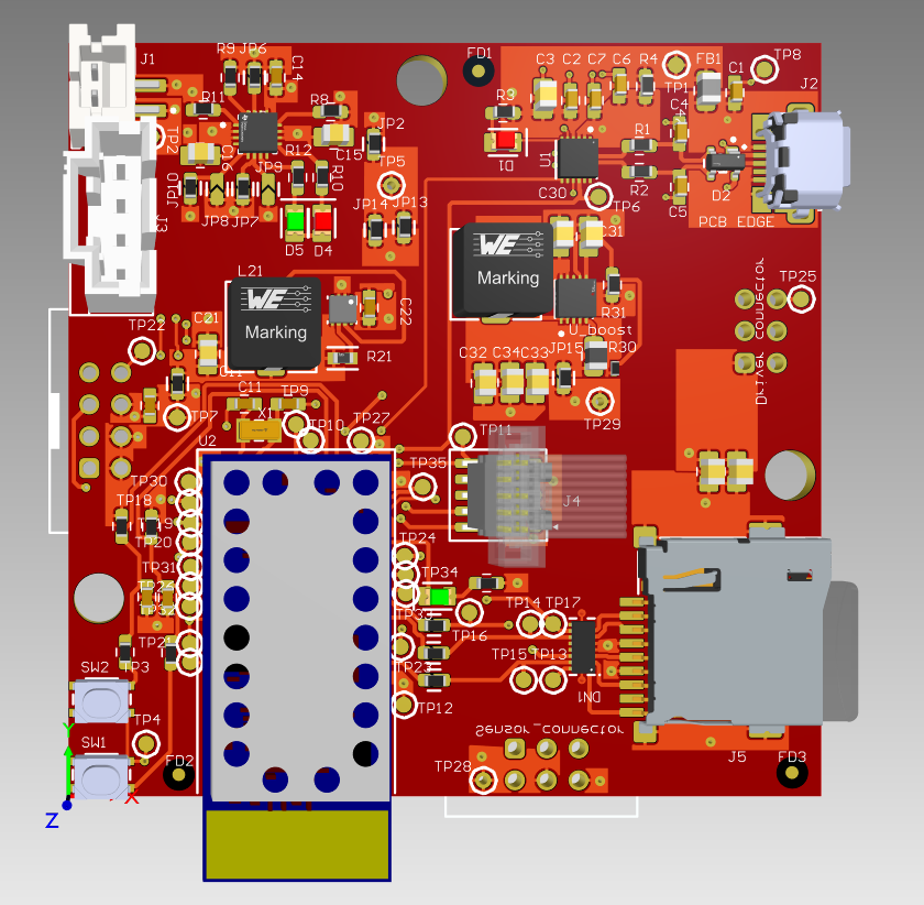
The Altium Board design in 3D view
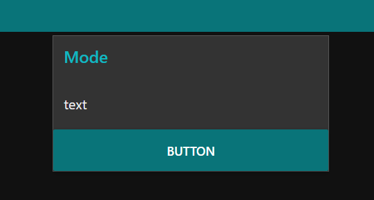
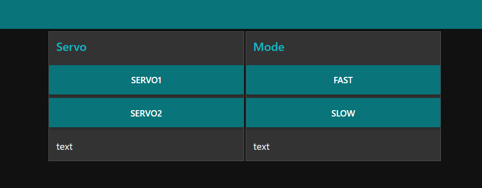
Node-RED dashboard
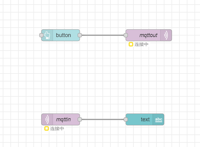
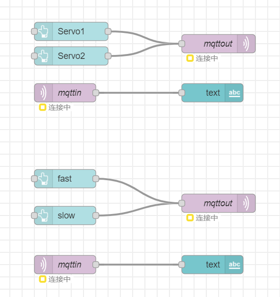
Node-RED backend
This screenshot was taken on a local server since Azure is disabled for our group. Deployment is not possible.
Block diagram of your system