a14g-final-submission-t15-comfortzone
a14g-final-submission
* Team Number: 15
* Team Name: ComfortZone
* Team Members: Zhuojun Chen, Weichen Ma
* Github Repository URL: https://github.com/ese5160/a14g-final-submission-t15-comfortzone
* Description of test hardware: laptop, prototype
1. Video Presentation
Project Video Demo
2. Project Summary
Device Description
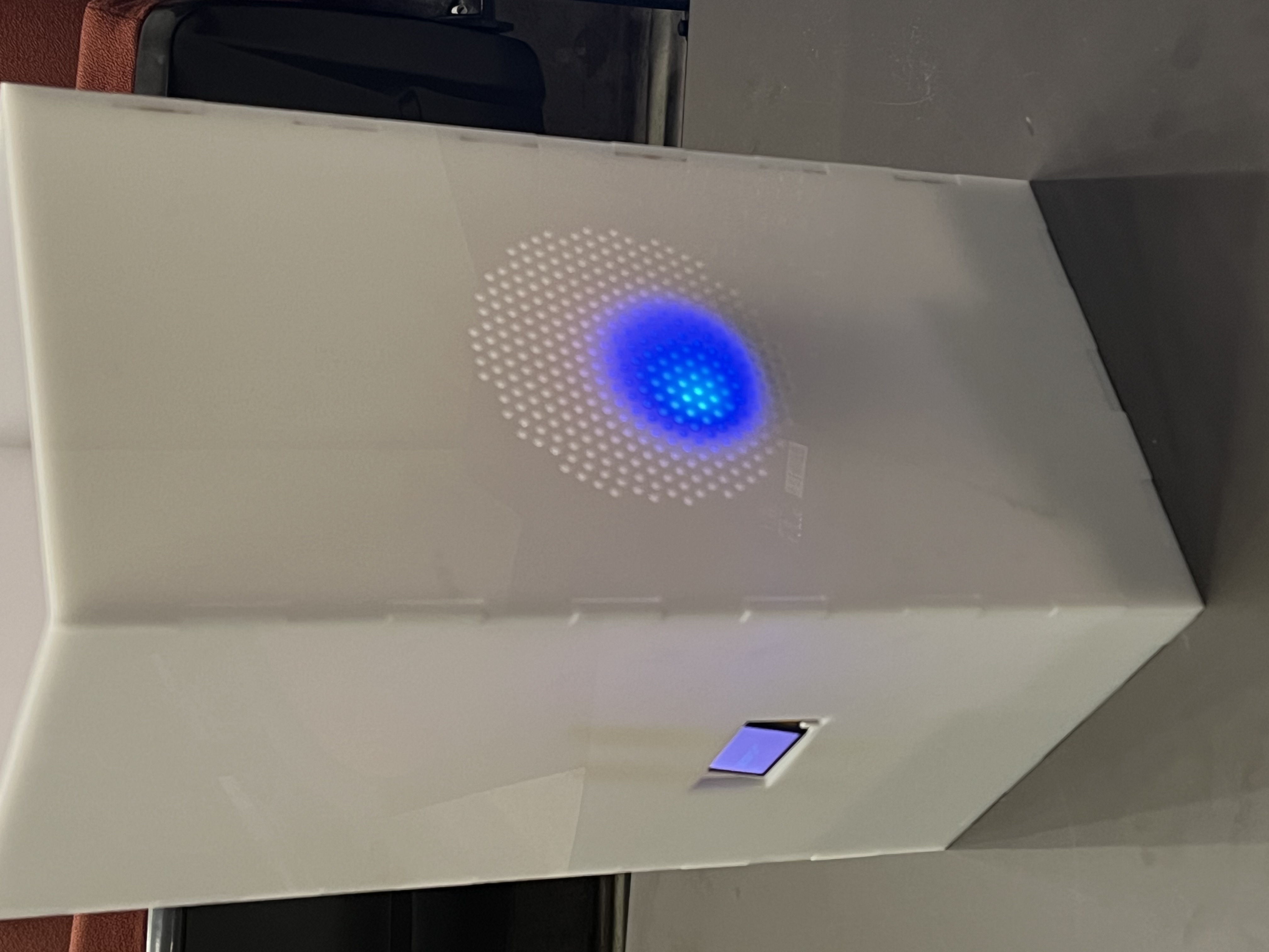
ComfortZone proposes a solution for a better indoor environment. This device will constantly monitor the indoor temperature and humidity and adjust according to users’ preference. With access to internet, the users can easily check the current temperature and humidity and set up their preferred levels on each. The device will automatically press the prefilled spray through venting holes when the preferred levels are not met. The usage on the prefilled spray will also be monitored so that the users can be notified when the volume runs low and refill in time.
Inspiration
The inspiration for our project comes from common daily scenes in everyone’s life. Whether we are working in office, studying in class, or resting at home, we want to be able to stay cool and hydrated abd feel comfortable. So we think of a “housekeeper” that can take care of this and automate responses that suit our needs when staying inside. By delegating these simple yet non-trivial tasks as much as possible to this “housekeeper”, we improve the quality of living experiences without much hassle.
Device Functionality
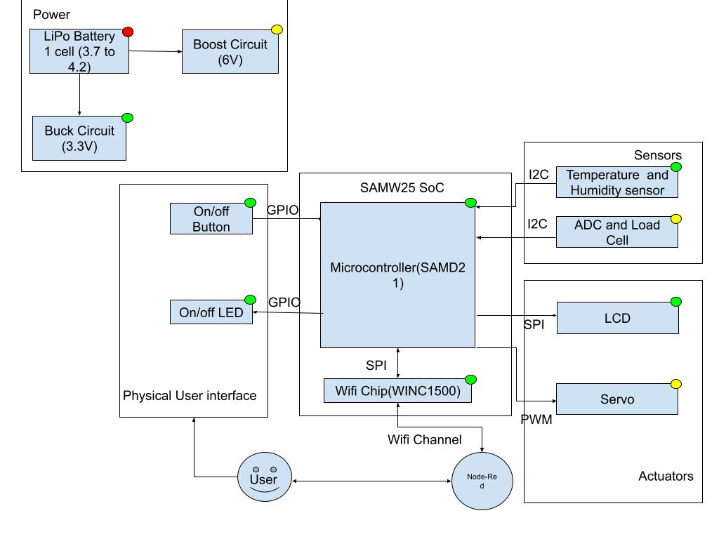
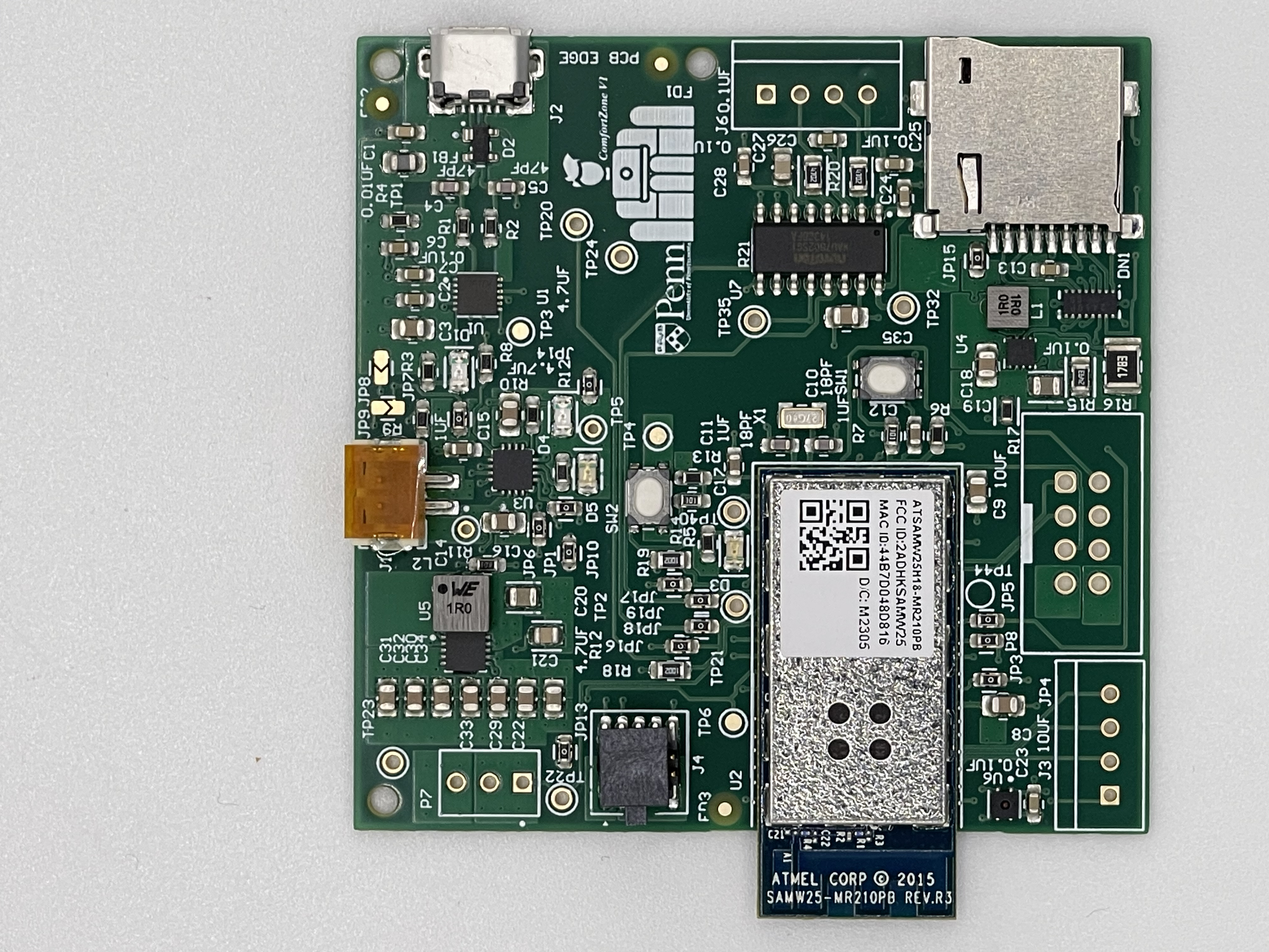
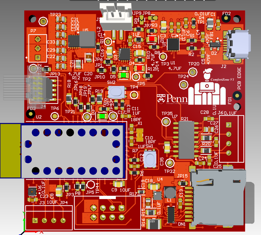
Our Internet-connected device is designed on a 4-layer Printed Circuit Board(PCB) with a complete power system, serial communication interface, memory storage, sensors and actuators. Additionally, part of the user inferface is designed and hosted on cloud. Below we provide a detailed rundown of each component and functionality.
Power Supply and Regulation
- The power supply of the device come from 2 source: single-cell 4.2V LiPo battery and USB
- LiPo Charger connects to both power sources (USB preferred when both connected)
- 3.3V buck circuit and 5V boost circuit are connected through LiPo Charger and provide stable voltage sources to all peripherals on PCB
Serial Communication Interface
- FTDI circuitry bridges between USART channels from SAMW25 and USB port for serial communication
- ESD Protection circuit is in place for USB data protection
- MCU directly communicate through serial interface to other devices’ USB port
Memory Storage
- SD Card is mounted on PCB and connects to MCU through SPI
- Writing to and reading from SD card with MCU’s Non Volatile Memory
- Application images stored in SD Card for update
Sensors, Actuators
- Temperature and Humidity Sensor: Monitors the indoor temperature and humdity and send to MCU through I2C
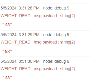
- Load Cell and ADC Module: Measures the weight of the spray and send to MCU through I2C
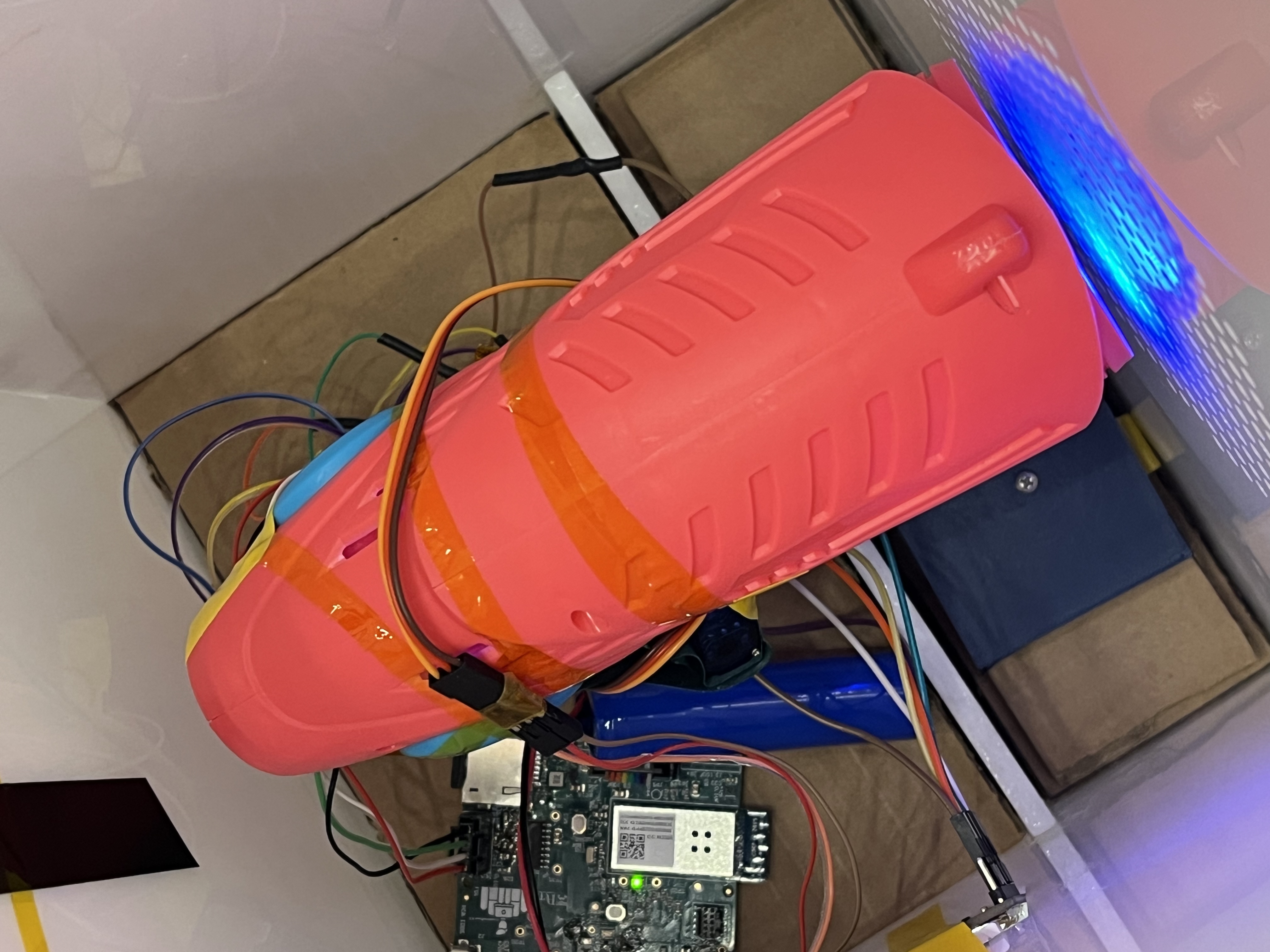
- Servo: Precise and controlled movement to press the spray
- LCD Display Screen: Displays the current temperature and humidity and indicates usage status
WiFi Module and Cloud
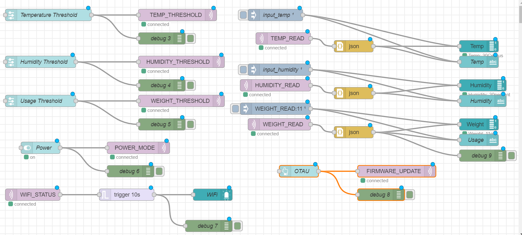
- WiFi Module connects to MCU to communicate sensor data and users’ messages through MQTT broker
- Node Red User Interface on Azure server to
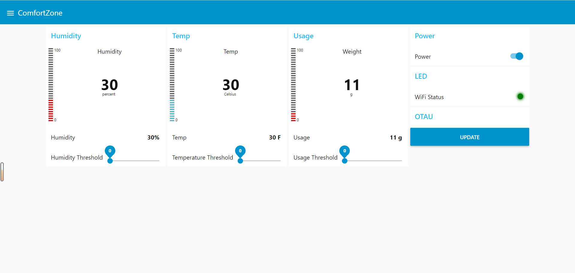
- display real-time temperature, humidity, and weight
- set preferred thresholds for temperature, humidity, and weight
- switch on/off power and monitor Internet connectivity to device
- over-the-air firmware update
Operating System
- FreeRTOS is used to facilitate efficient task operations
The integrated hardware and firmware design ensures the seamless and synchronized operations of multiple functions intended for our device. Leveraging a variety of tools for development and testing, ComfortZone serves as a reliable and user-friendly real-world application device in IoT.
Challenges
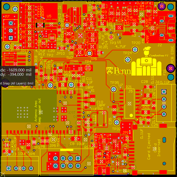
- Laying out all components and circuitry onto PCB in a compact design and following all design rules at the same time require careful design. To achieve this, we prioritized components that require complex interconnect, routing their pins first and surrounding them with their connected peripherals to minimize routing length. For routings that are less important such as those used for testpoints, we took advantage of the bottom plane to reduce area used in the top plane.
- The firmware driver for one of the sensors we found was complicated and when it did not work on our sensor, we did not know how to debug. To solve this, we read through the datasheet carefully and wrote our own simple driver.
- The SERCOM pad mapping for 2 of our pins in our prototyping is reversed and cannot work as expected. Since these 2 pins are not connected to other peripherals, we adapted the pin configuration in firmware without changing the hardware to make it work.
- After each driver works correctly on its own, they failed after integrated together. We carefully combined and divided different operations within tasks and tuned for their delays and priorities to ensure all tasks can work with relatively low latency on FreeRTOS.
- We sent our casework design for 3D printing but was notified that the dimensions were too big to be 3D printed. Therefore, we switched to lasercutting for each piece of our original design and used press-fitting and gluing to assemble the casework.
Prototype Learning
Lessons
- For PCB prototyping, following the example layout of development boards of components can improve the probability of success in our own design.
- Reading through the datasheets and application notes of components can help us gain valuable insights in both hardware specifications and firmware functions.
- If the footprints of critical components cannot be found, we can draw our own footprints and link them to recommended components from the datasheet. Need to be very cautious about replacing a component with one that is not recommended in the datasheet.
- Pin mapping requires careful planning for peripherals that work under specific protocols including I2C, SPI, UART.
- Before testing for firmware, check for correct hardware connections on PCB prototype leveraging logic analyzer and osciliscope and cross-examining with schematics and datasheet.
- When prototyping for electrical connections, we need to also think about mechanical integration so that both can work well when the design is finished and room for adjustability is small.
Changes for rebuild
- Take more in-depth research on sensors and actuators available to use. Our current design use a toy servo to control the spraying. Later on in the project development we have found out that there is a specific humidifier module that can be controlled by a GPIO and directly turn liquid into its vapor form, which is more closely aligned with our prototype funciton and easier to integrate.
- Current casework does not take into account of shielding the PCB and other eletric components from the water from the spray. Casework should be designed in a more electrically safe manner to isolate all the electrical components away from the water spray.
Next Step
There is much room for further development in both firmware, software and mechanics to optimize for power, efficiency, security, and user interface.
- Use TCC to refine task operation periods
All current tasks run in a non-terminating loop. To get more refined control of operational periods, we can configure TCC to only trigger the operations based on specified timer ticks to control task timing and reduce power consumption. - Turn off all peripherals when not running
Once the TCC is configured to run in lower frequency, we can send most, if not all, peripherals into sleep mode to further reduce power consumption when they are idle. - Extend Cloud User Interface functionality for more flexible control
Use real time from the Internet to allow users to set up specific time for turning on and off the device as they need. - Add extra layer of security for users Configure username and password validation for communicating to the Cloud server so that only authorized users can connect to their devices
- Further integrate the casework
Add mounting points for different electric components and PCB to hold them in place and provide shield so that they are electrically safe and away from water.
Takeaway from ESE5160
Through semester-long development of ESE5160, we have completed the entire end-to-end development of a Internet-connected product prototype. With the lectures, assignments, and a variety of datasheet and documentation reading, we have learnt many important topics in embedded system and IoT design.
- Product design starts from idealization and research on available components that can achieve functions for our design.
- Power and current requirments for each of the components used need to be considered into power budget and used for power architecture of our prototype.
- Based on the protocols and functionalities used for each component, designated pin assignment follows the datasheet of microcontroller chip to fulfill specific function requirements.
- Structure the schematics hierarchically help maintaining clear net relationships
- Adhere to PCB design rules using Altium Designer’s design rule check (DRC) to prevent any potential manufacturing and connection issues
- Write good documentation and double check for Bill of Materials before manufacturing release
- FreeRTOS, a Real-time operating system, leverage between tasks through queues to achieve synchronized operations for achieving complex functionalities.
- Develop CLI tool through serial communication help in debugging and testing for functionalities in firmware development stage.
- Writing drivers for communication protocols including I2C, SPI, and UART vary and require careful configuration
- Bootloader is an integral part of updating firmware and occupies different memory space than application code
- SD card uses a file system and FATFS APIs facilitate managing its file system
- MQTT utilizes Publish-Subscribe model for communication between devices and cloud and cloud server help with hosting not only MQTT broker but application images and other media to be downloaded through the Internet.
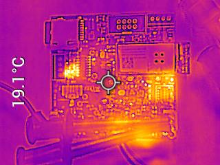
- PCB board bringup includes power system evaluation, E-load testing, thermal testing, as well as debugger programming.
Project Links
- Node-Red
- Frontend: http://13.90.207.71:1880/ui/#!/2?socketid=FEulCUVg47lGnAQtAAAB
- Backend: http://13.90.207.71:1880/#flow/bf052231e125d8be
- Source Code: https://github.com/ese5160/a12g-firmware-drivers-t15-comfortzone
- PCBA: https://upenn-eselabs.365.altium.com/designs/B509742C-FE00-4DFA-B87E-58B0CF9B060D
3. Hardware & Software Requirements
Hardware Requirements Review
- HRS 01: Requirment met. Said ADC was used.
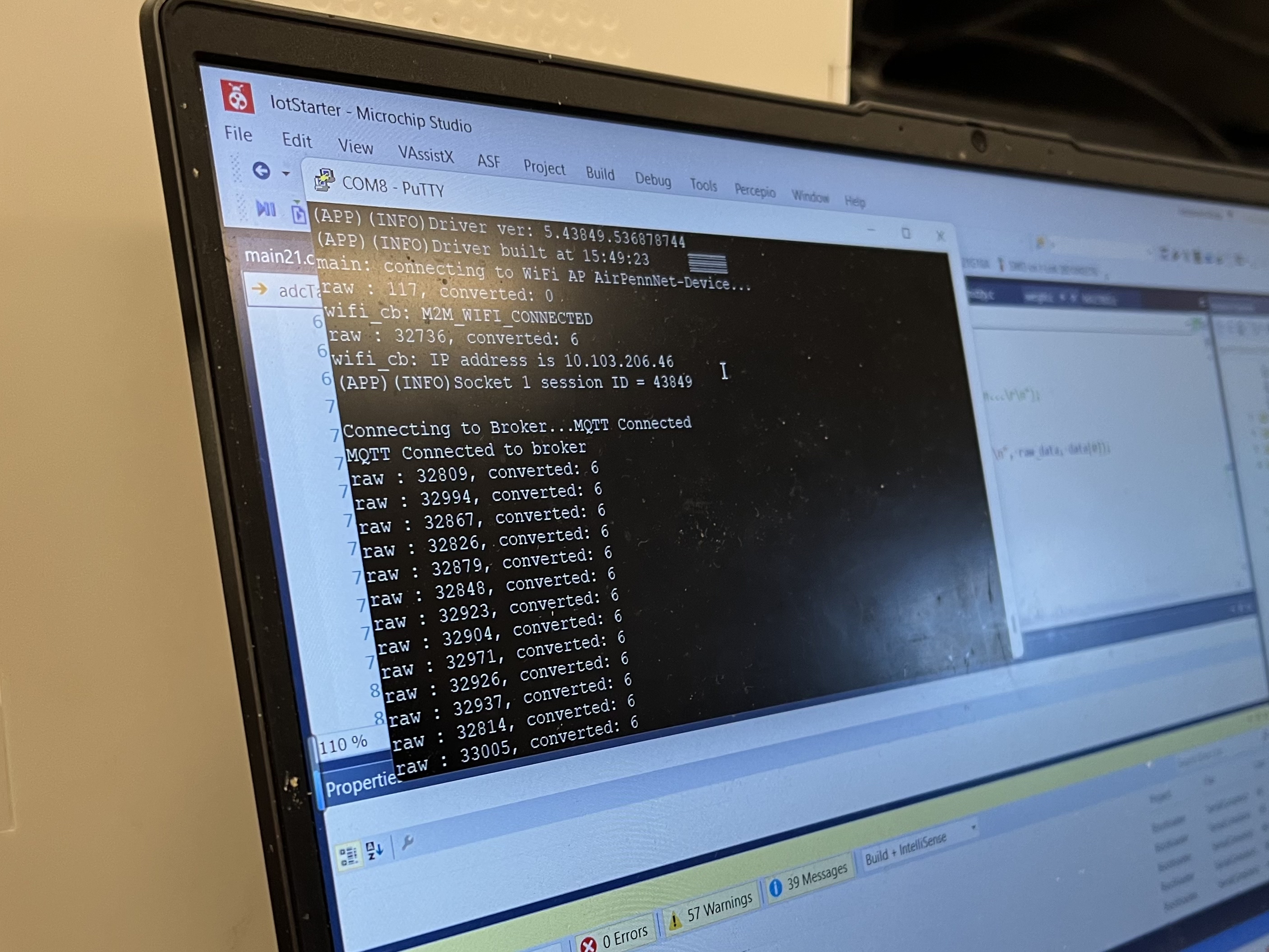
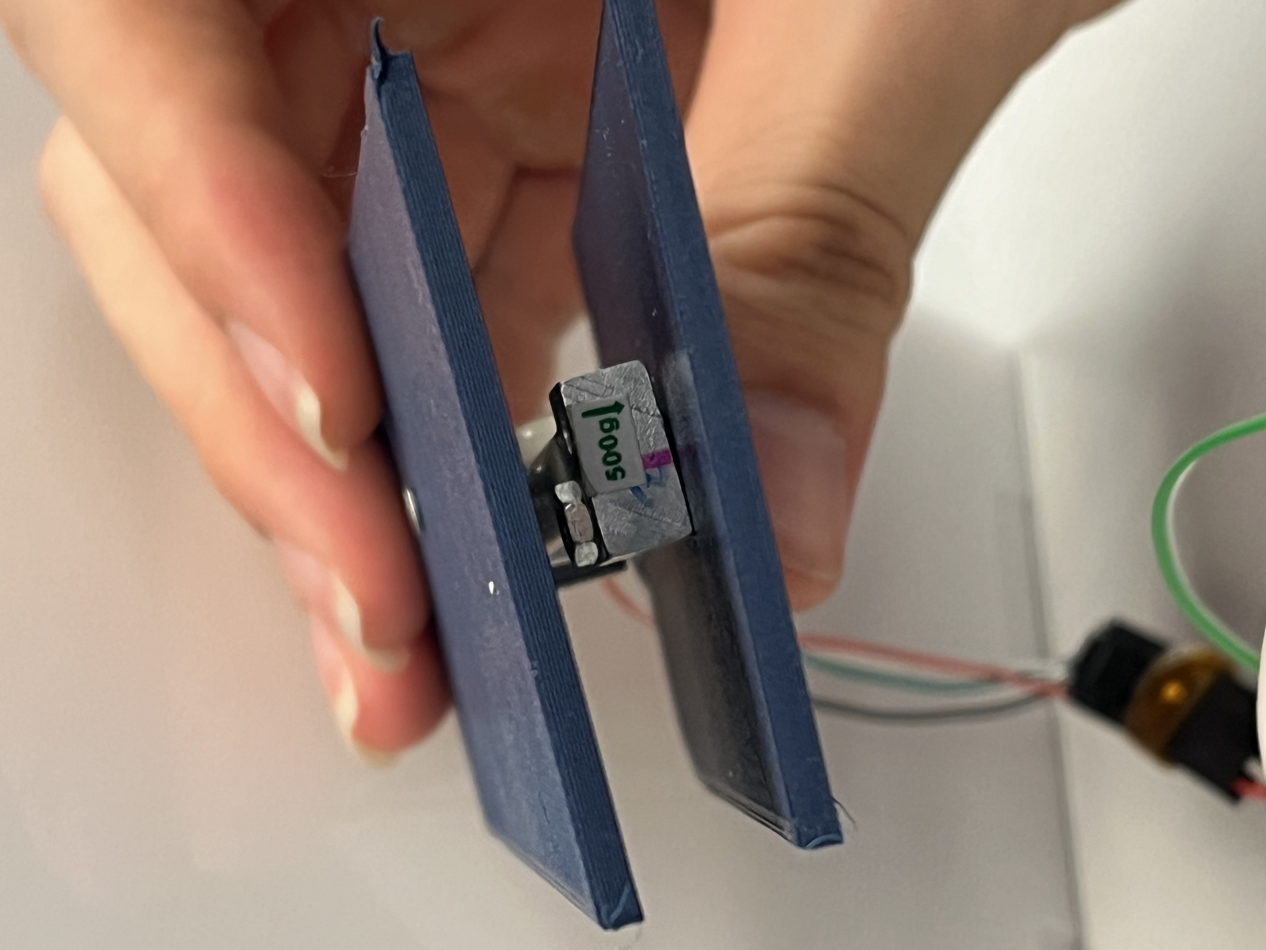
- HRS 02: Adjusted. The load cell is changed to one detecting up to 500g because the load we are using does not exceed 500g.
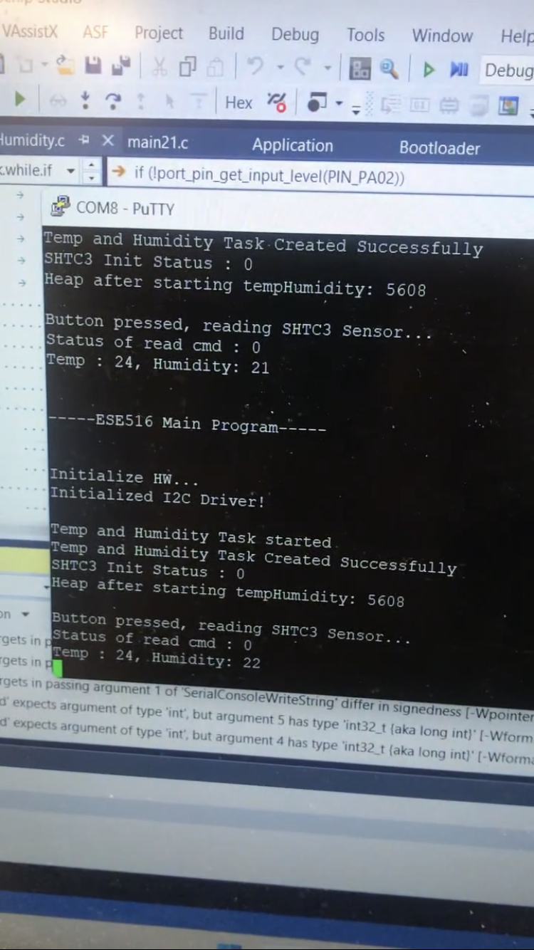
- HRS 03: Requirement met. The sensor performed within the specified temperature and humidity accuracy against known humidity and temperature values to validate the accuracy.
- HRS 04: Requirement met. Said servo was used.
- HRS 05: Reuqirement met. Said Li-Ion battery was used.
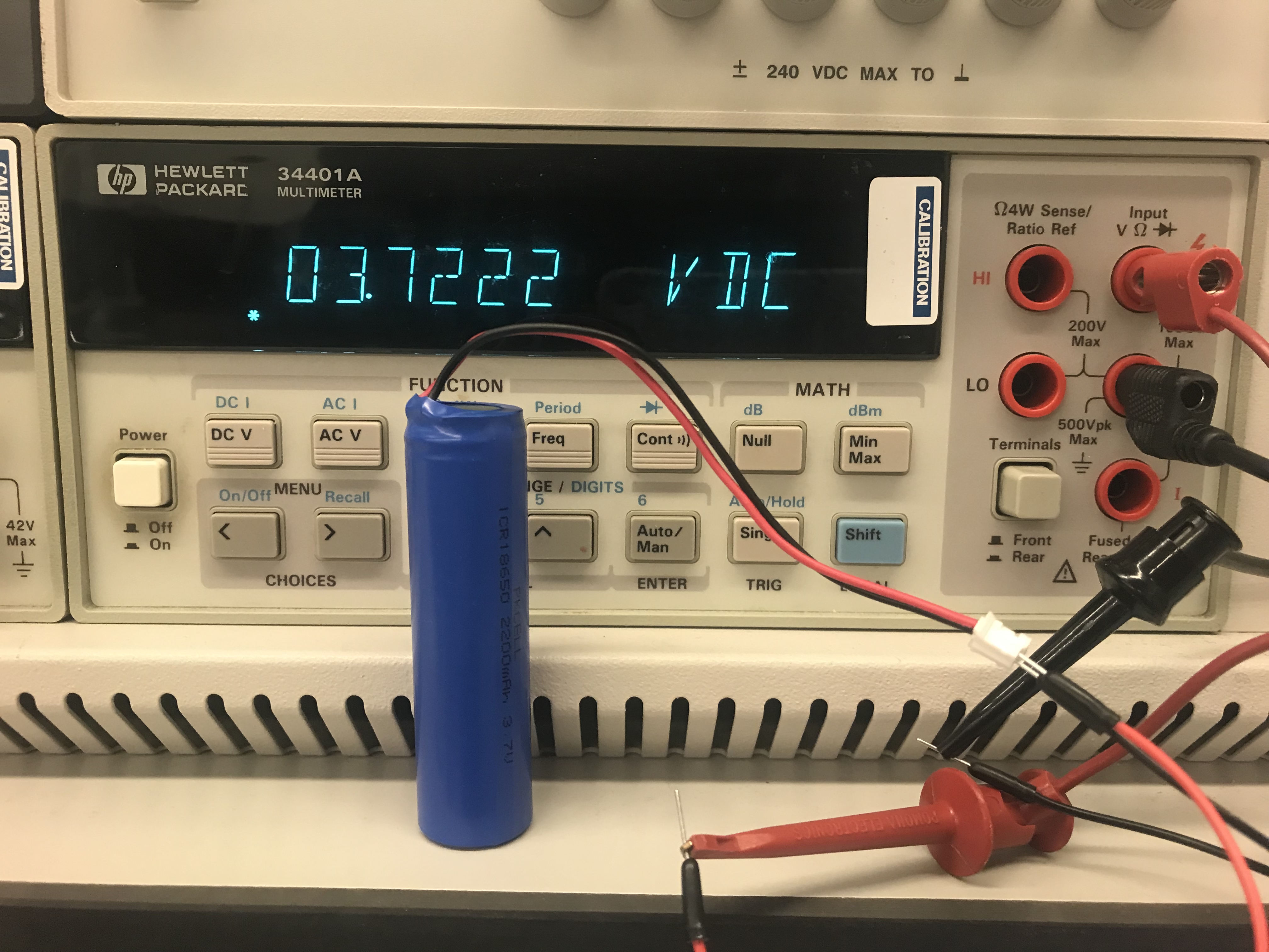
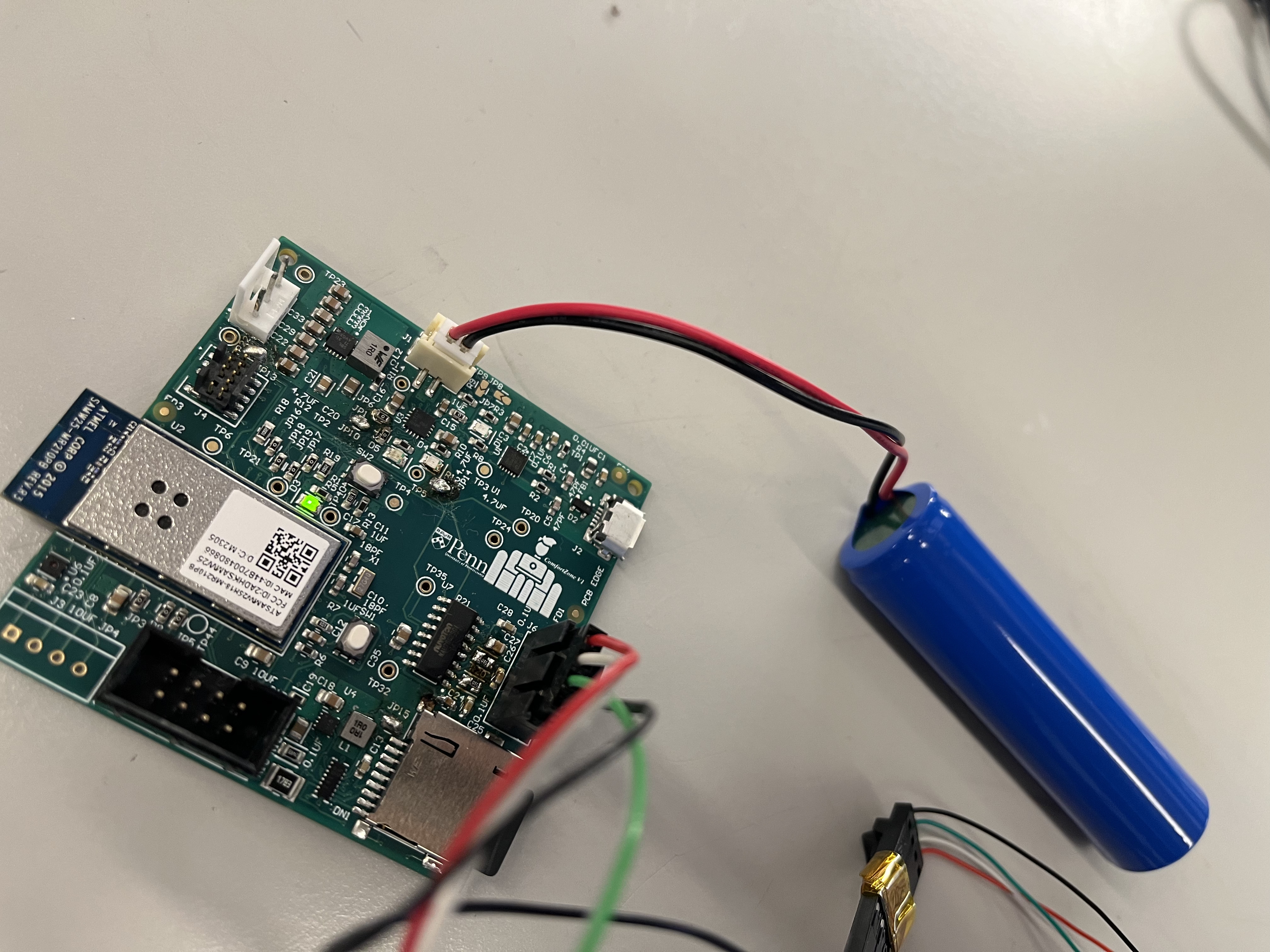
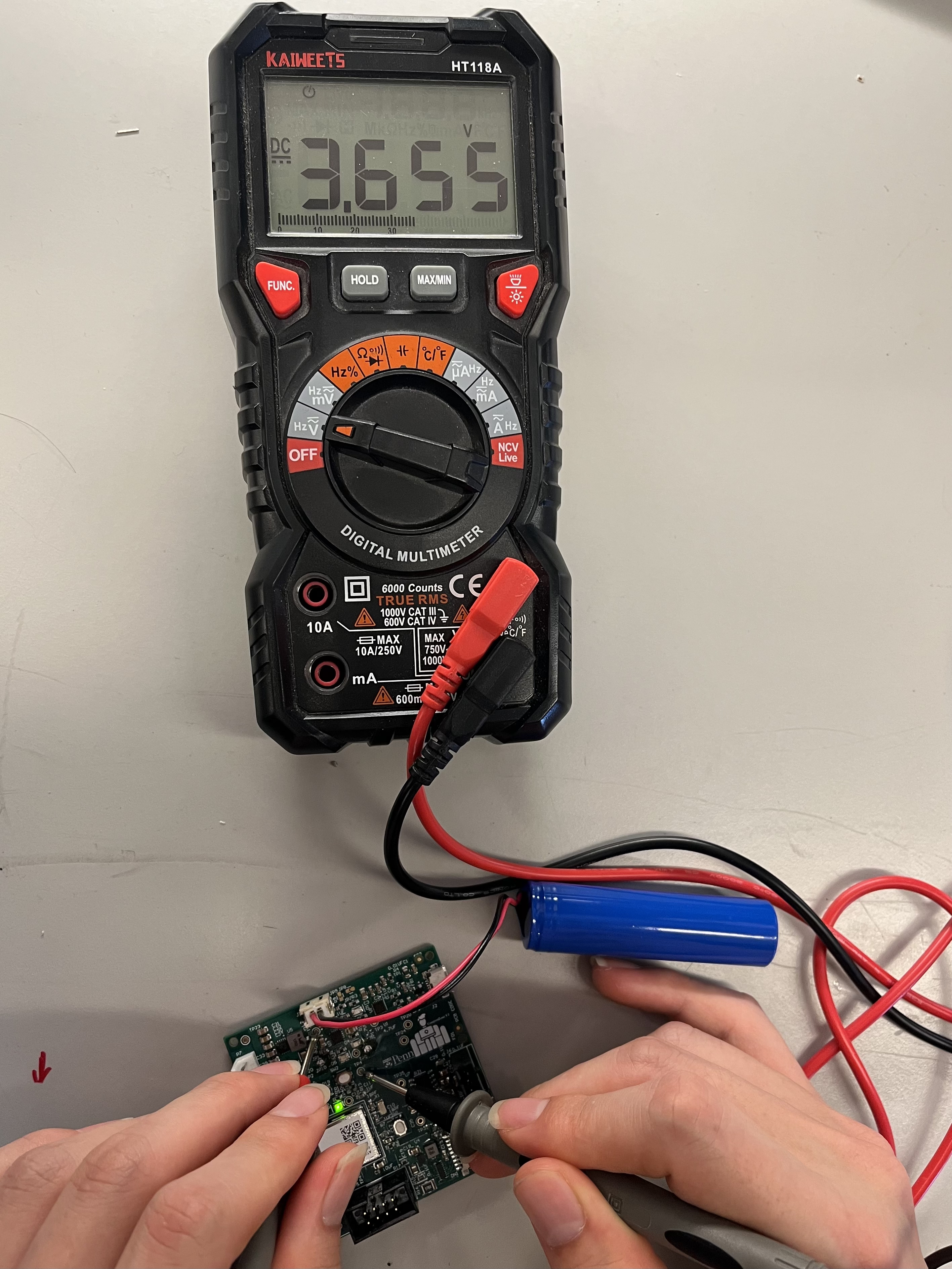
- HRS 01: Requirment met. Said ADC was used.
Software Requirements Review
- SRS 01: Requirement not met. The sensor is continuously reading the value.
- SRS 02: Requirement met. Node-Red receives the message sent.
4. Project Photos & Screenshots
Prototype
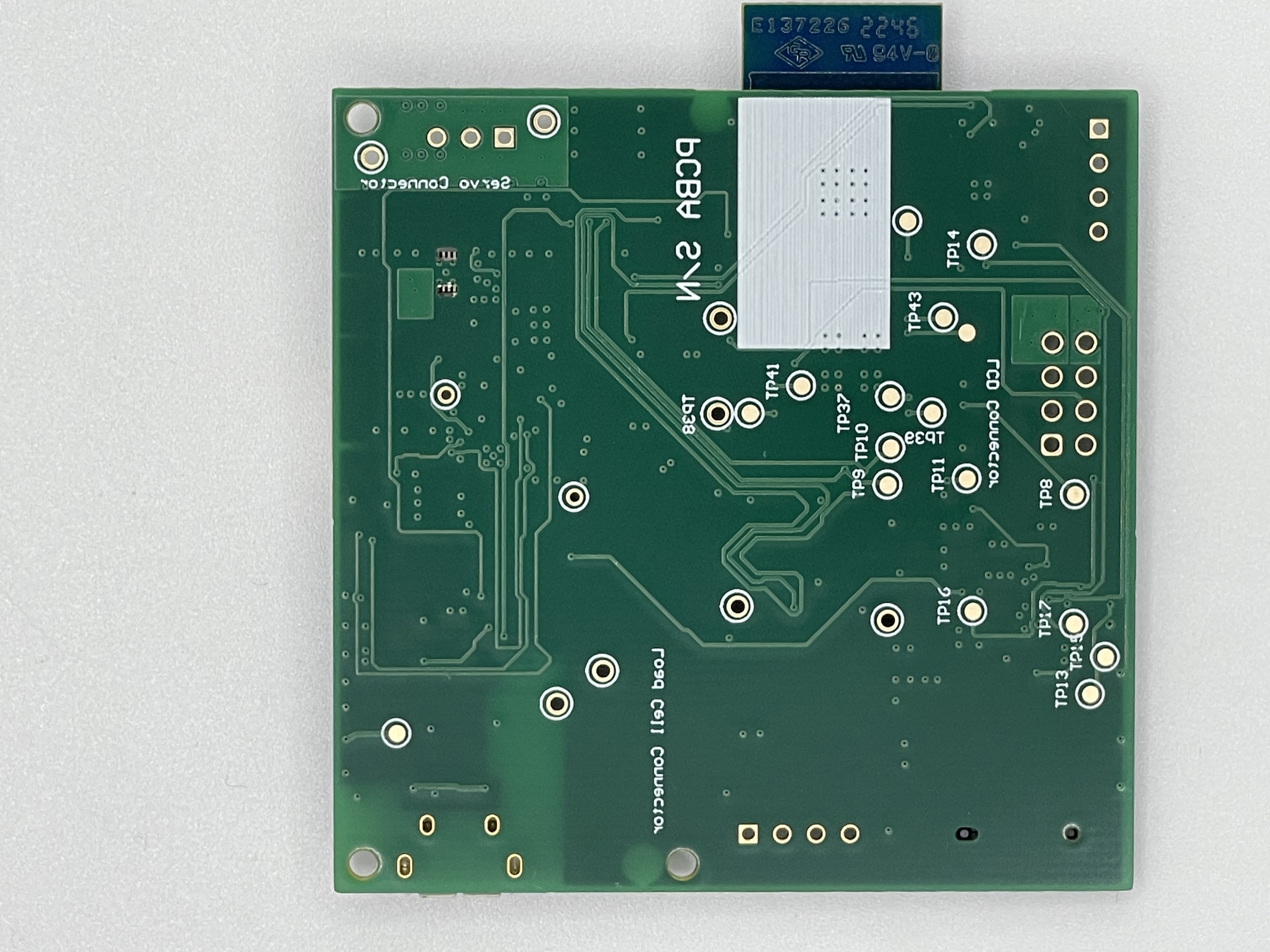
PCBA
Thermal Camera
Altium Design
Node Red
Block Diagram
