Product Scanner! ESE516 TEAM5
Team Number: 5
Team Name: Pruduct Scanner
Team Members: Tianshu Wang & Jin Qian
Github Repository URL: https://github.com/ese5160/a14g-final-submission-t05-product-scanner
Description of test hardware:
SAMW25 Microcontroller,
SHTC3-TR-10KS Sensor,
1.8" Color TFT LCD with SPI Interface,
Tiny Code Reader from Useful Sensors,
ADA1201 Vibrating Motor,
3.7V Li-Ion Battery
1. Video Presentation
2. Project Summary
Device Description
Our device serves as a supermarket product scanner, allowing customers to scan QR codes to access item information such as location, name, and stock quantity displayed on an LCD screen. Supermarket staff can monitor the products scanned by customers and their respective locations via the terminal web page. Moreover, employees can also track the temperature and humidity within the supermarket to assess if environmental adjustments are necessary.
Inspiration
The inspiration for this product mainly came from what we saw in supermarkets with large indoor areas (such as Costco and Walmart). When we shop in these supermarkets, we often encounter the situation where we want to buy a small product, but it is difficult to find the product because the supermarket is too large. Therefore, our team wants to design a device that can scan the product's QR code. After scanning the QR code, the specific location of the item you are looking for, as well as the price and remaining quantity information can be displayed. Additionally, this product has a built-in temperature and humidity sensor. This information will be sent back to the computers of supermarket staff, allowing them to monitor the environment in the supermarket and adjust the air conditioning temperature in time to ensure that the products are fresh enough to prevent deterioration. Therefore, the target customers of this product are the operators of these large supermarkets. It can be installed on supermarket shopping carts for customers to use.
Device Functionality
We have designed a device capable of scanning QR codes to retrieve product information while simultaneously monitoring indoor temperature and humidity. The data collected by this device can be transmitted over the network and displayed on the terminal web page using Node-RED. Our device consists of two sensors and two actuators. The sensors include an SHTC3 temperature and humidity sensor and a QR code scanner, while the actuators comprise a vibrating motor and a color LCD screen.
The overall workflow of our product is as follows:
- When a customer uses the device to scan a QR code, the QR code scanner identifies the scanned QR code and provides vibration feedback to the customer using the vibrating motor.
- The information retrieved from the scan is displayed on the LCD screen, showing the product's location, name, and inventory quantity.
- The location information of the scanned items is also uploaded to the Node-RED UI interface, allowing access to this information via devices such as computers or smartphones.
- Finally, the SHTC3 sensor installed within our device continuously monitors the temperature and humidity of the supermarket. This information is uploaded to the Node-RED UI interface for display. Additionally, if the temperature exceeds a certain threshold or the humidity reaches a high level, a pop-up warning will appear on the page, alerting staff to adjust the air conditioning settings in that area.
Challenges
In general, we faced four challenges and partly solved them in the right way.
1. LCD Configuration
Our initial challenge stemmed from the SPI configuration for the LCD screen. Upon configuring the LCD, we encountered difficulty as the designated pin ports of the MCU couldn't be configured with SPI. This oversight likely occurred due to not verifying the configuration in Atmel Start during PCB design. Instead, we relied on the SPI line indicated on the MCU in the Altium schematic.
Prototype Learnings
Reflecting on the process of building and testing our prototype, where we created and utilized our own PCB, several critical lessons emerged. First, the utility of test points was evident; they greatly facilitated troubleshooting and functional verification at various stages. When selecting pins, it is essential to ensure they align with the intended use and hardware compatibility, which is the most significant part of implementing PCB in the real project.
Next Steps
In terms of hardware, our next step is to re-modify our own PCBA board and solve the previous wiring and connector problems so that the board will no longer have any physical errors and will be more convenient for subsequent use. At the same time, a module for communicating with the Internet is installed on the PCBA to improve the functionality of this product.
Takeaways from ESE5160
What did you learn in ESE5160 through the lectures, assignments, and this course-long prototyping project?
- The first and most important thing is to learn how to design PCBA boards through Altium, and know how to place components and correctly connect circuits.
- Learned how to test and debug hardware through oscilloscopes and other instruments, find circuit faults and find ways to solve them.
- Learned how to design a UI interface for your own product through node-red. Through node-red, I can try to think from the customer's perspective on how to design the UI interface to be more concise and easy to use.
- Learn how to write code correctly to ensure that various components have enough heap space to allow them to run in an orderly and continuous manner.
Project Codebase Links
3. Hardware & Software Requirements
Hardware Requirements
- HRS 01 - SAMW25 Microcontroller: Our project is based on a self-designed PCB. The MCU of this PCB is the SAMW25 microcontroller, with J-link used to flash the code into the PCB.
- HRS 02 - SHTC3-TR-10KS Sensor: In compliance with HRS 02, our system employs the SHTC3-TR-10KS sensor, which detects a wide range of temperature (-40 °C to 125 °C) and humidity (0 to 100 %RH). The typical accuracy is ±2 %RH for humidity and ±0.2°C for temperature, but our software configuration displays accuracy to ±1°C for temperature and ±1 %RH for humidity due to integer data type limitations.
- HRS 03 - 1.8" Color TFT LCD with SPI Interface: The implementation of the 1.8" Color TFT LCD with an SPI interface in our project was crucial for displaying detailed product information. This LCD module communicates with the microcontroller through the SPI, ensuring swift and stable data updates.
- HRS 04 - Tiny Code Reader from Useful Sensors: The Tiny Code Reader captures and interprets QR codes effectively, with an LED indicator that signals the scanning process status. It communicates with the microcontroller via I2C, changing from blue to green upon a successful scan.
- HRS 05 - ADA1201 Vibrating Motor: The ADA1201 vibrating motor is integrated as a tactile feedback mechanism. It sends a vibration alert each time an item is scanned and when the user finishes shopping, enhancing the user experience with immediate physical feedback.
- HRS 06 - System Integration and Control: Our development team has implemented a system that integrates multiple hardware components to ensure smooth and efficient operation. The device operates on a 3.7V Li-Ion battery, with a tested continuous operational capability of at least 3 hours.
Software Requirements
- SRS 01 - QR Code Scanning and Processing: The Adafruit 5744 QR code reader scans QR codes on products with a response time of less than 2 seconds per scan. While the I2C protocol speed is assumed to be efficient, we lack tools to measure the exact speed, focusing on the operational performance.
- SRS 02 - Display Management: We manage a 1.8" Color TFT LCD screen with an SPI interface, capable of displaying product details. Current performance shows a refresh time of approximately one to two seconds, slower than the desired 500 milliseconds.
- SRS 03 - Temperature and Humidity Monitoring: The software interfaces with the SHTC3-TR-10KS sensor, collecting and transmitting temperature and humidity data every 5 seconds via MQTT to Node-RED for real-time monitoring and analysis.
- SRS 04 - Wireless Data Transmission: Using the SAMW25 Wi-Fi microcontroller, our system handles data transmission over a 2.4 GHz Wi-Fi network, supporting 802.11 b/g/n standards with a minimum data transfer rate of 150 Mbps. It seamlessly connects to various networks and interfaces with different server configurations.
- SRS 05 - User Interaction and Feedback: The ADA1201 vibrating motor is controlled by software to activate for 0.5 seconds for scan confirmations and alerts, with a slight delay in the vibration timing due to code issues but still delivering timely feedback.
4. Project Photos & Screenshots
Project Overview
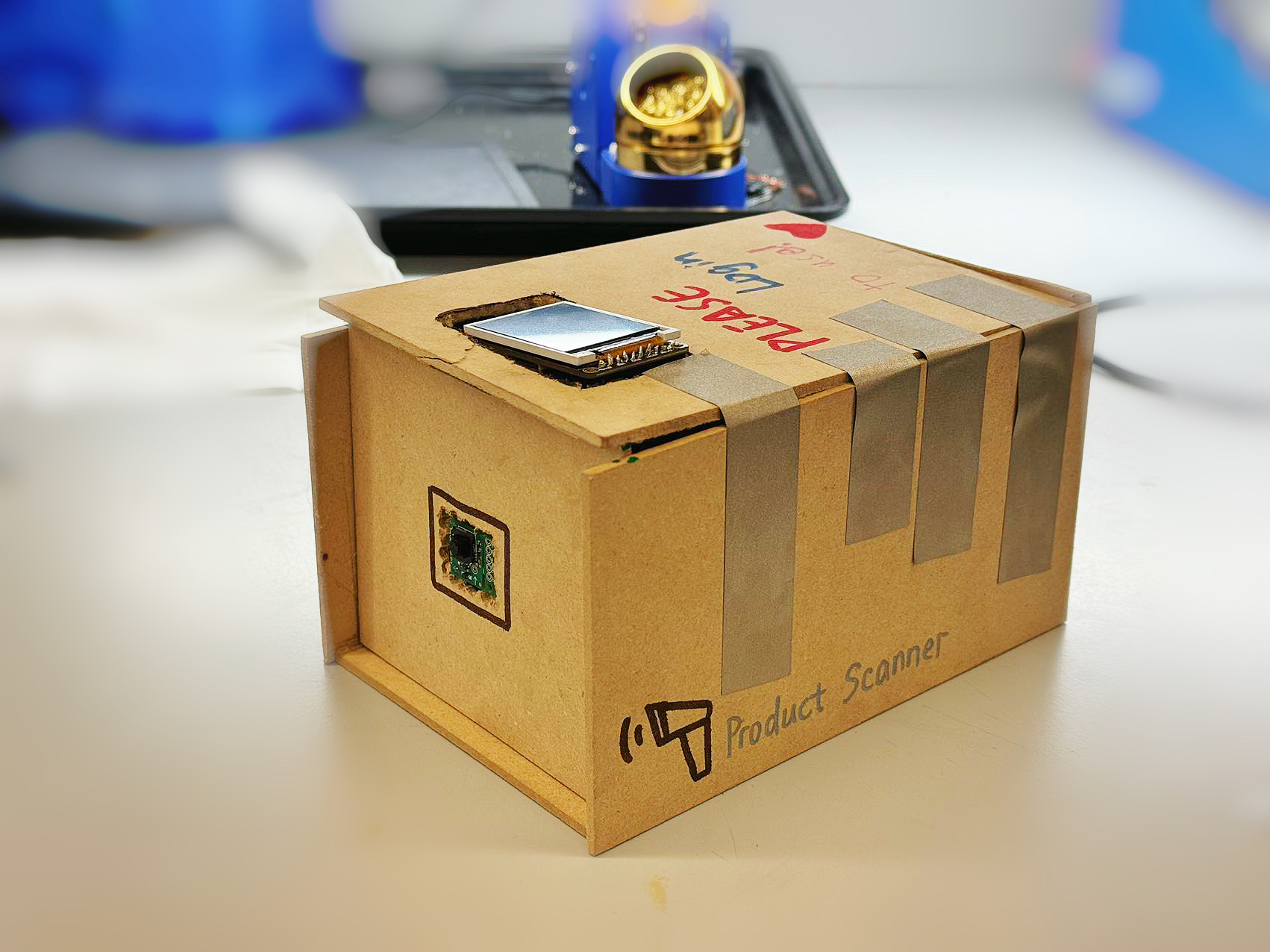
Description: Image of the complete final project setup, showcasing all external components like 3D prints, screens, and buttons.
Standalone PCBA - Top View
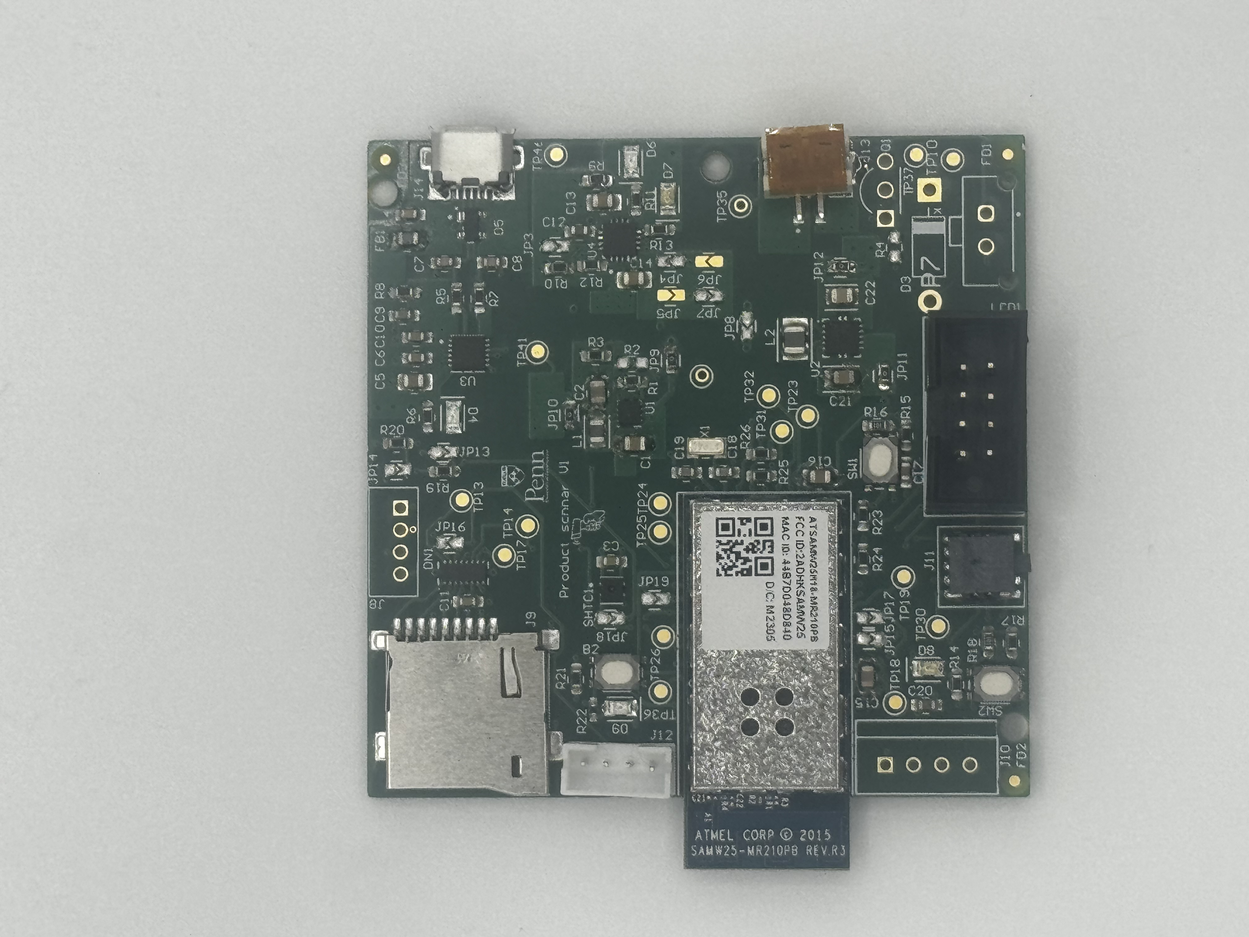
Description: Top view of the standalone printed circuit board assembly (PCBA).
Standalone PCBA - Bottom View
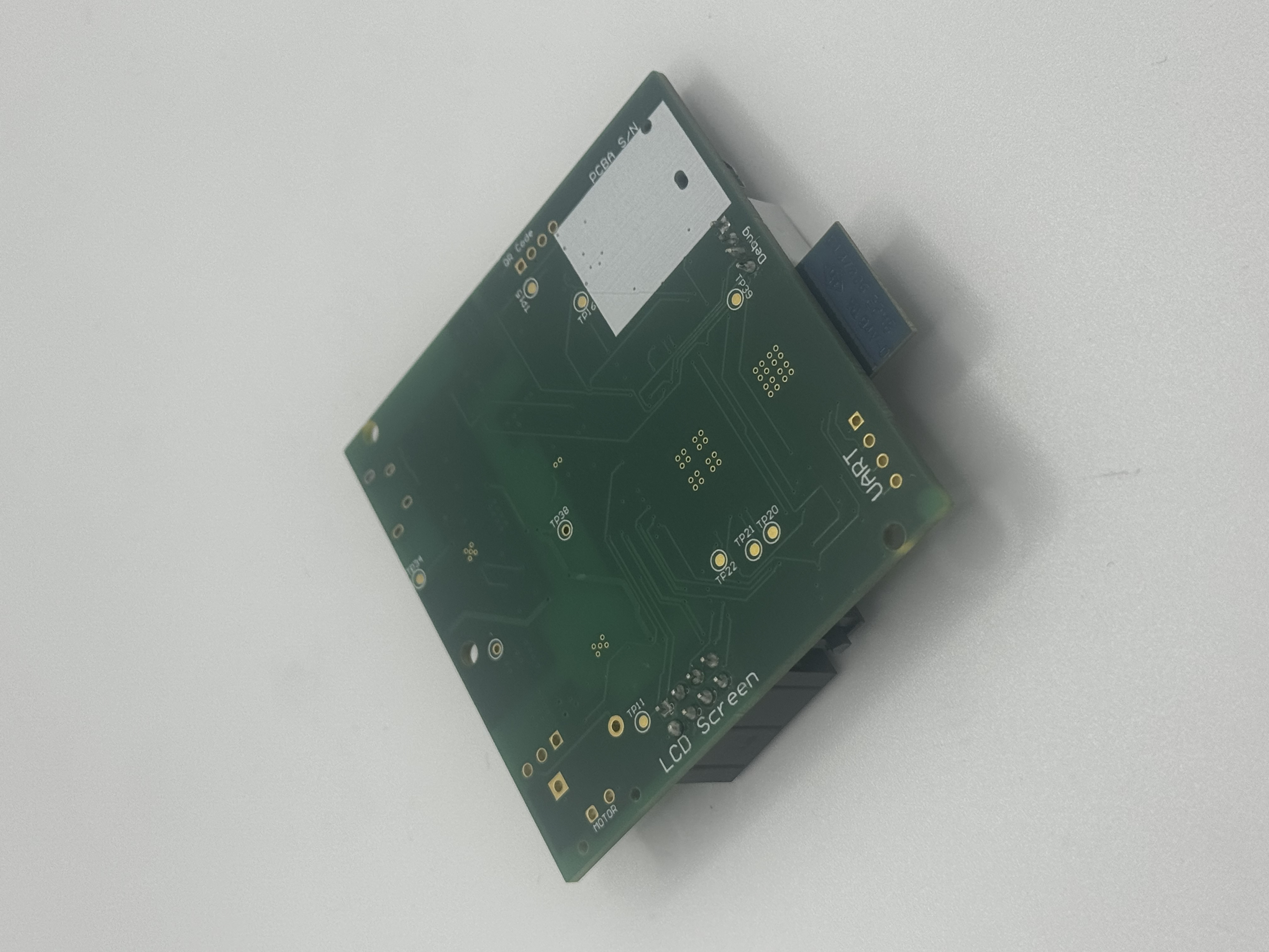
Description: Bottom view of the standalone printed circuit board assembly (PCBA).
Thermal Camera Images
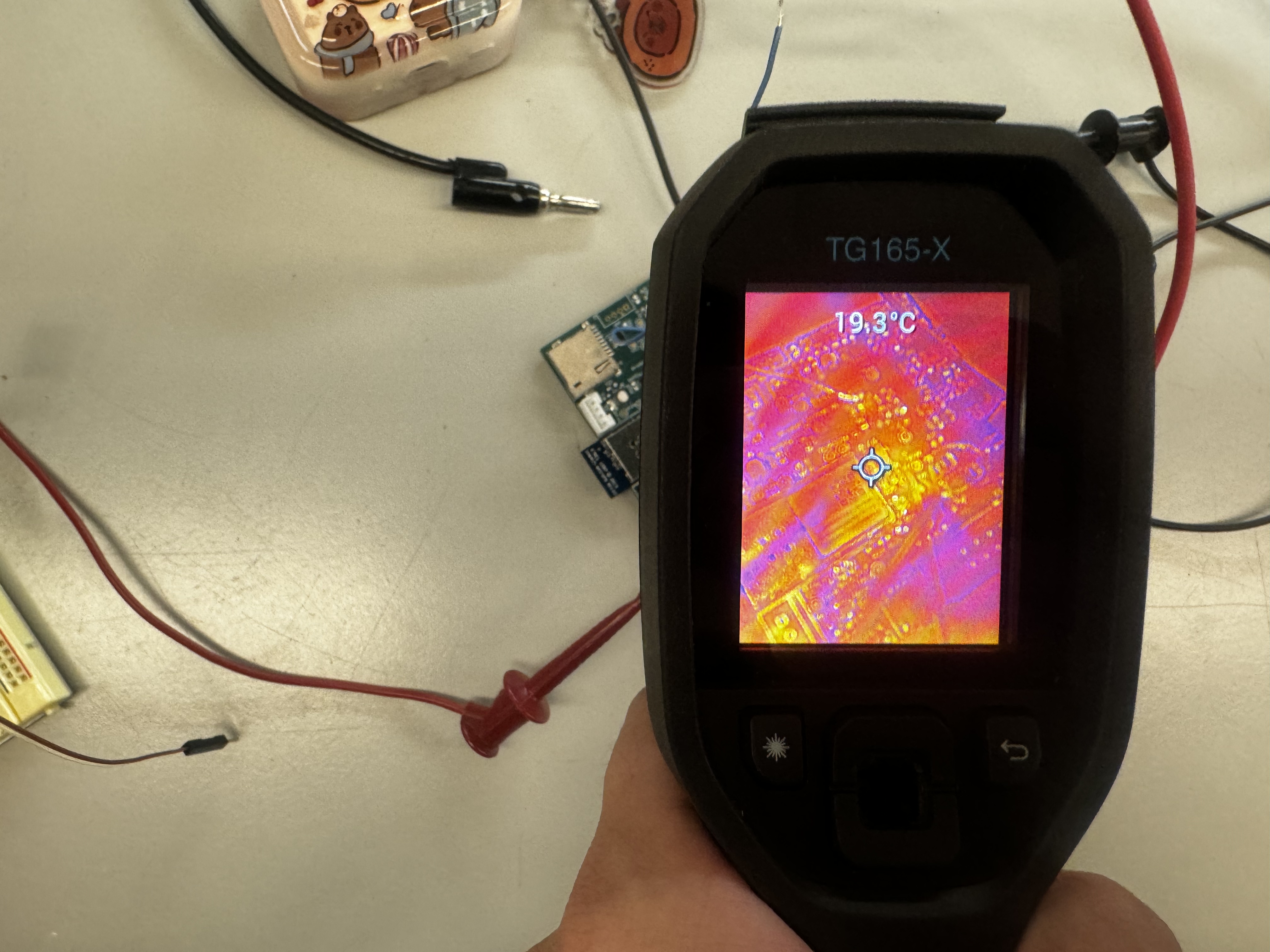
Description: Thermal camera image showing the board while running under load. Useful for assessing thermal performance and hot spots.
Altium Board Design - 2D View
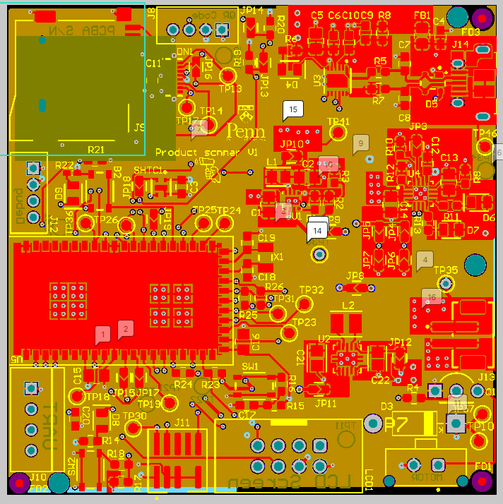
Description: Screenshot of the 2D view of the Altium board design, highlighting the layout and component placement.
Altium Board Design - 3D View
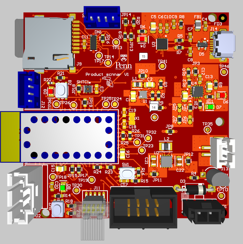
Description: Screenshot of the 3D view of the Altium board design, providing a realistic visualization of the assembled board.
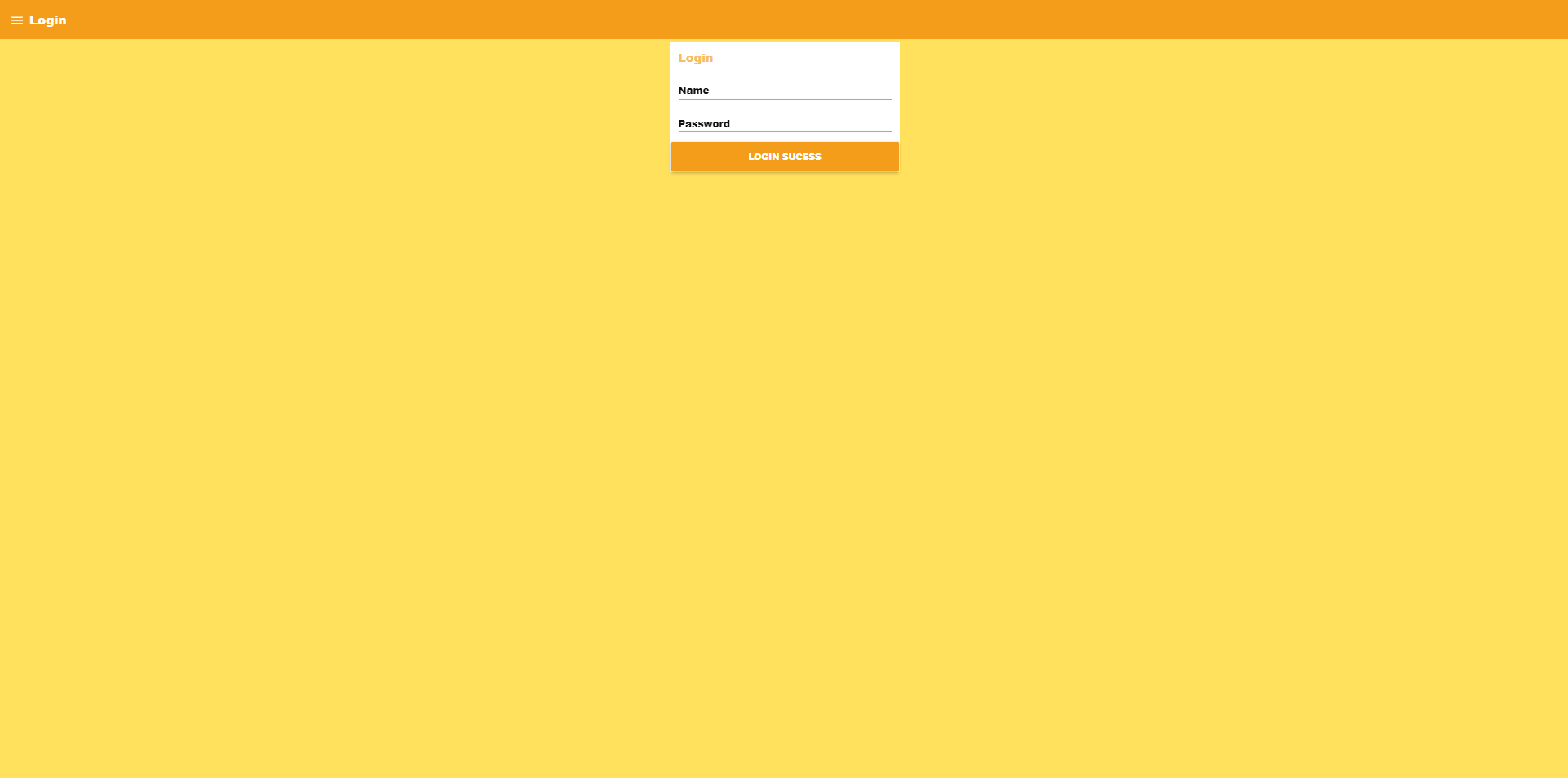
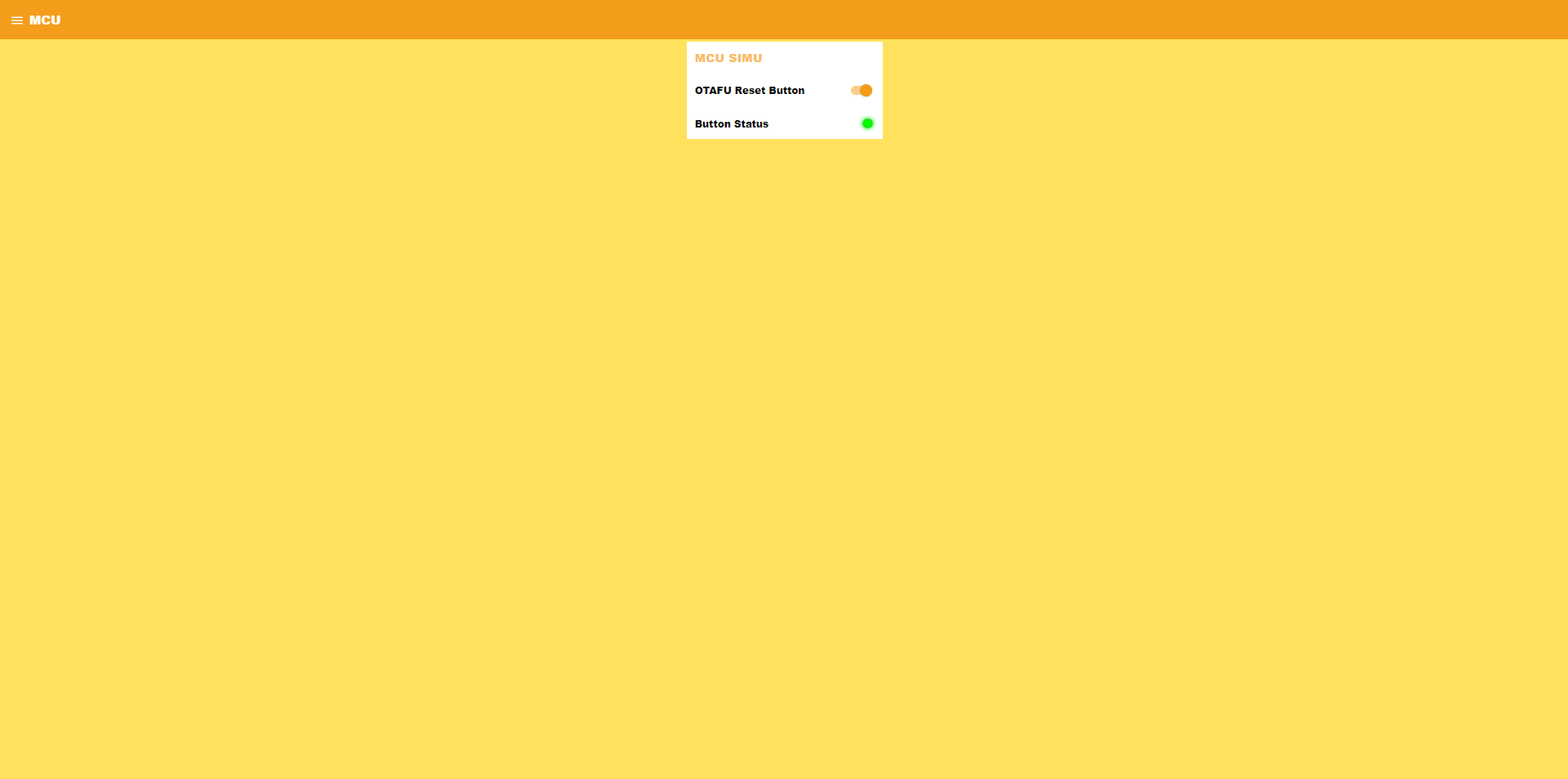
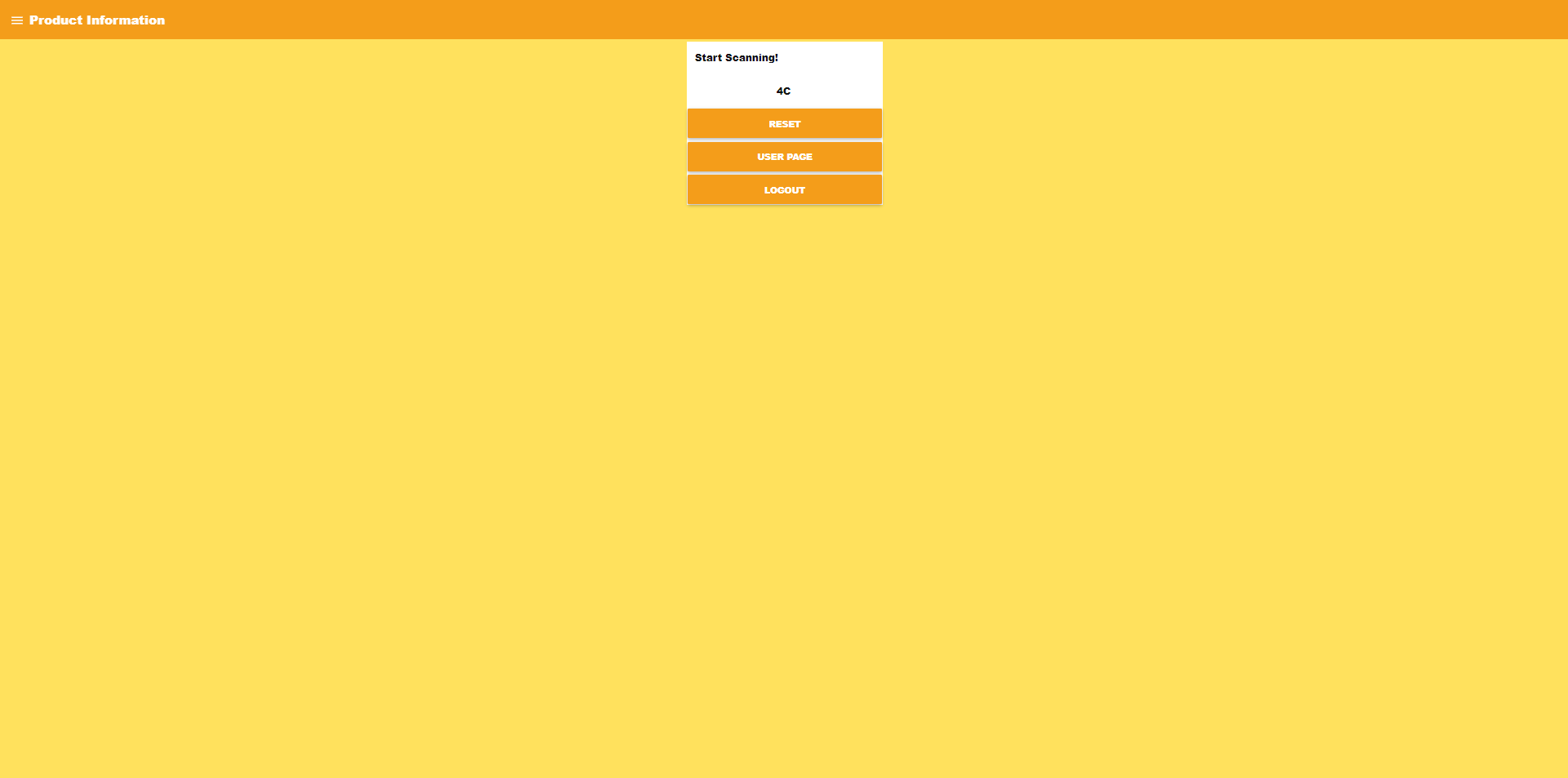
Node-RED Dashboard
Description: Screenshots of the Node-RED dashboard, displaying the user interface and data visualization components.
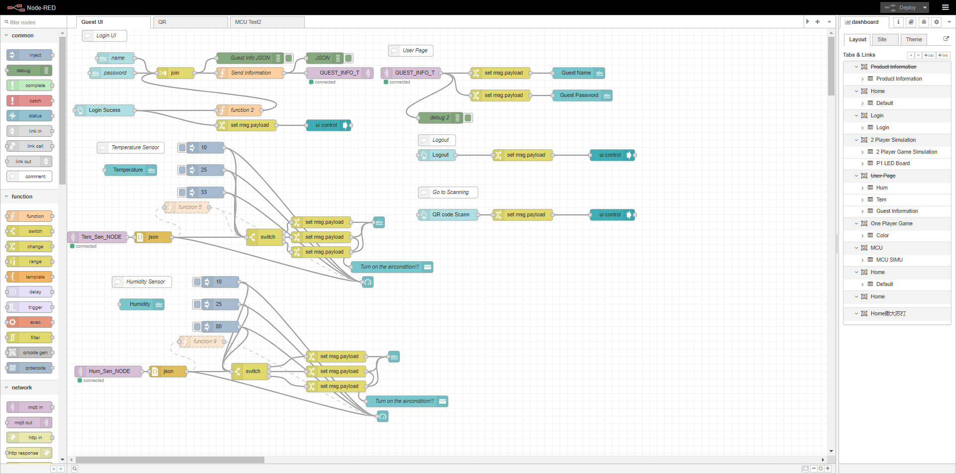
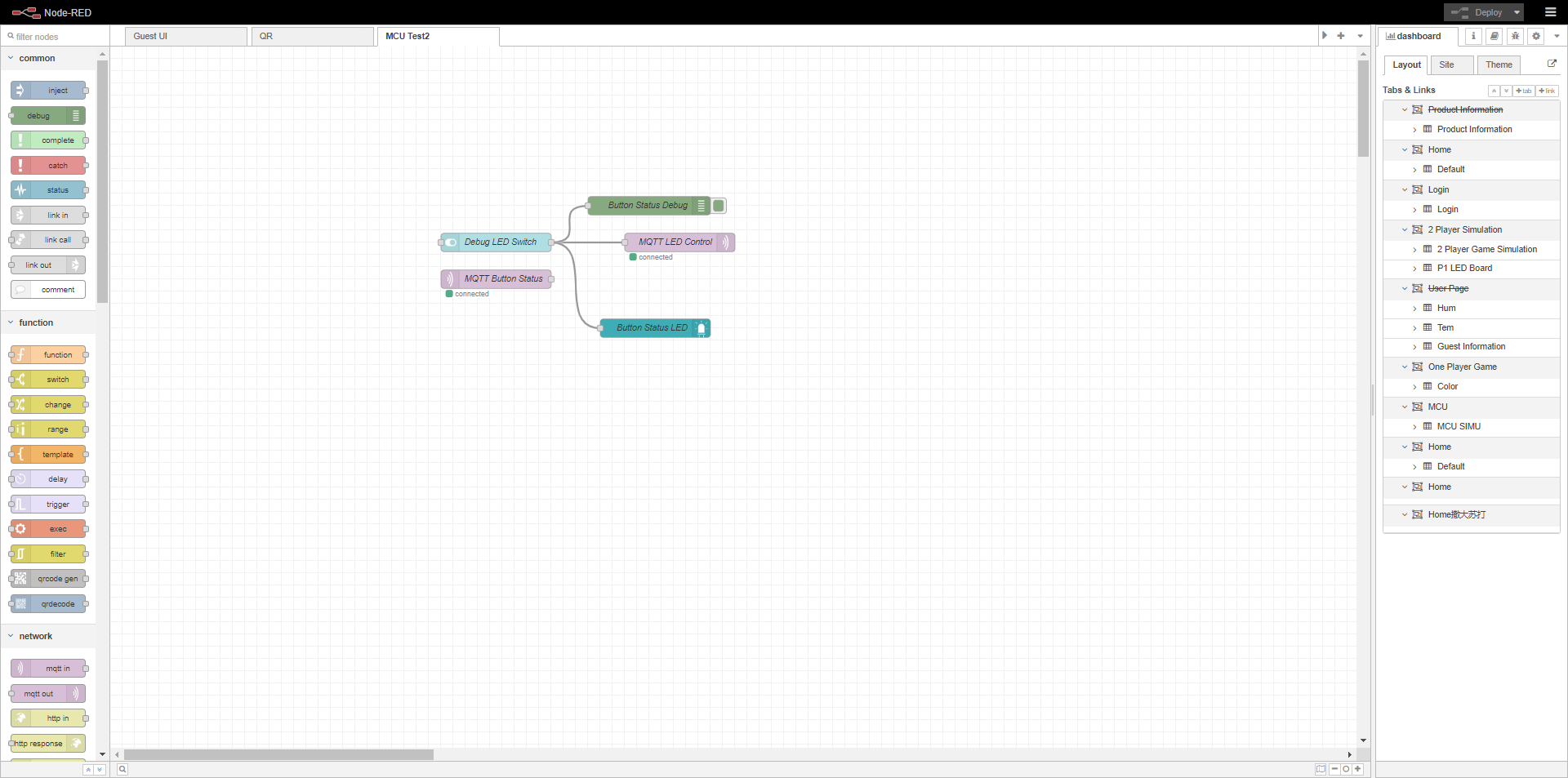
Node-RED Backend
Description: Screenshots of the Node-RED backend, illustrating the flow and logic used to process data.
System Block Diagram
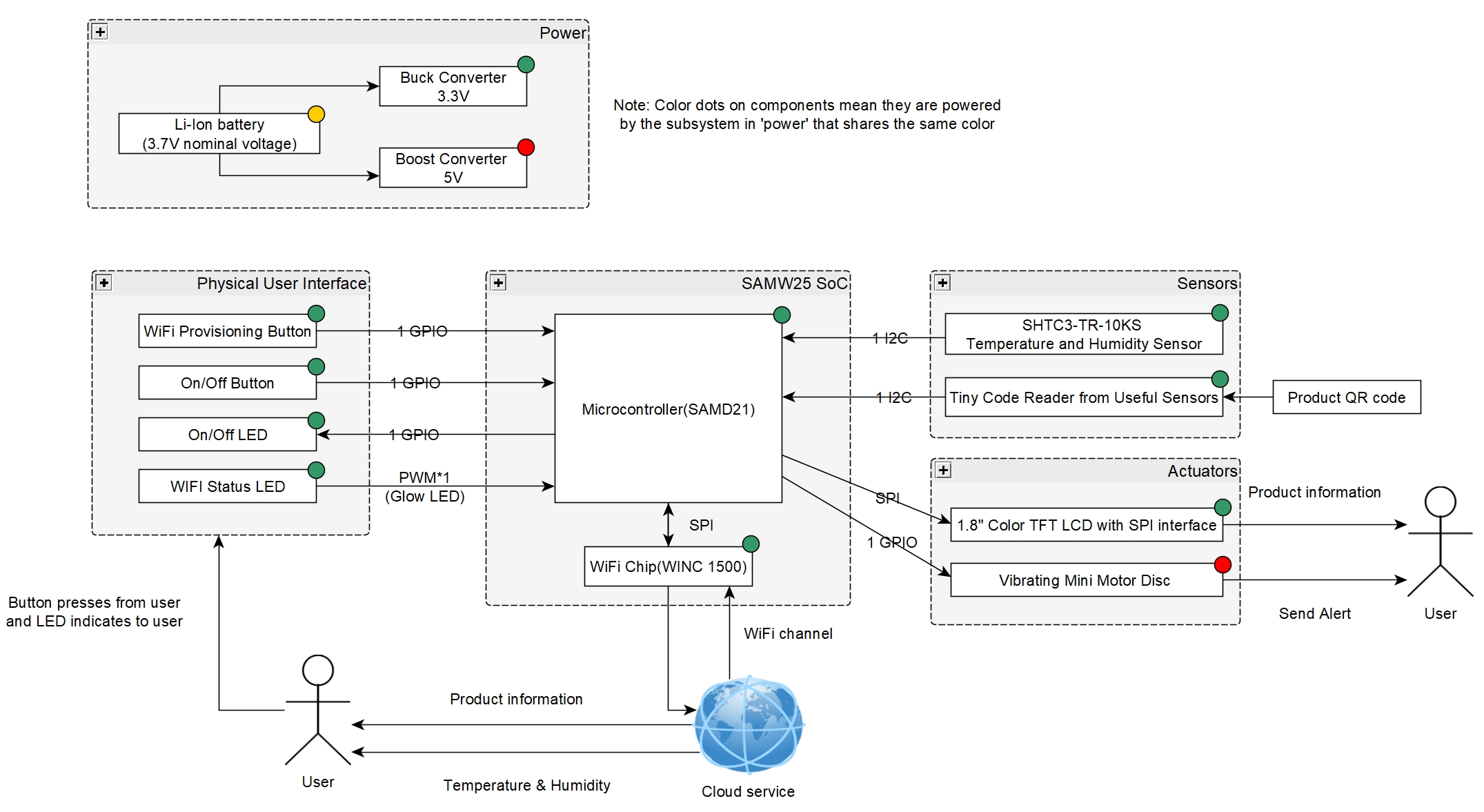
Description: Updated block diagram of the system, reflecting changes and integration details from the semester.
5. Project Codebase Links